
Electro-hydraulic combined braking system with retardance braking function

A slow braking, electro-hydraulic compound technology, applied in electric braking systems, braking transmissions, brakes, etc., can solve the problems of limited braking capacity, small braking torque, etc., to reduce the frequency of use and reduce pollution Effect

Inactive Publication Date: 2015-08-12
SHANDONG JIAOTONG UNIV
View PDF5 Cites 12 Cited by
  • Summary
  • Abstract
  • Description
  • Claims
  • Application Information

AI Technical Summary

Problems solved by technology

[0004] The purpose of the present invention is to solve the problem that the motor braking output braking torque is small and the braking capacity is limited in the traditional electro-hydraulic composite braking system, which leads to the frequent use of hydraulic braking, and provides a braking system with retarding An electro-hydraulic composite braking system with a braking function and a control method thereof, the electro-hydraulic composite braking system integrates three braking forms of motor braking, retarding braking and hydraulic braking, has the advantages of less braking noise and dust, and Advantages of high dynamic comfort and convenient installation

Method used


Image

  • Electro-hydraulic combined braking system with retardance braking function
  • Electro-hydraulic combined braking system with retardance braking function
  • Electro-hydraulic combined braking system with retardance braking function

Examples


Embodiment Construction

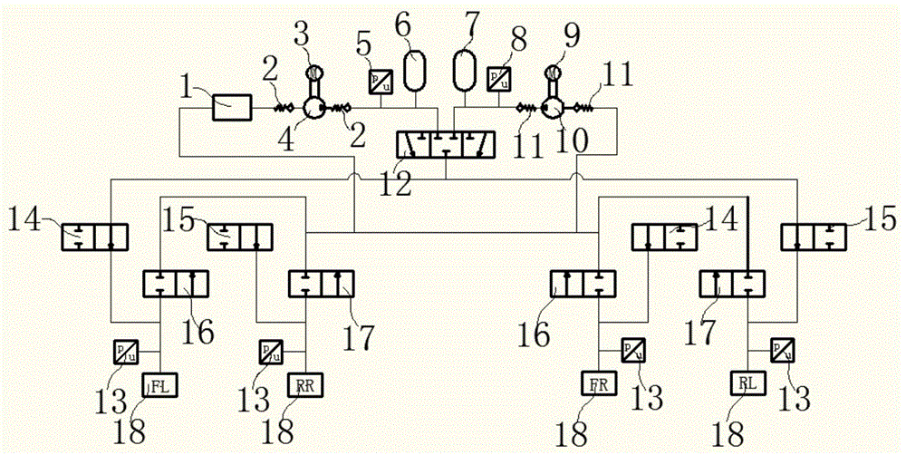
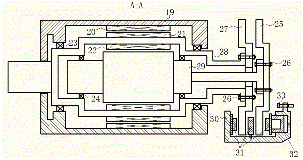
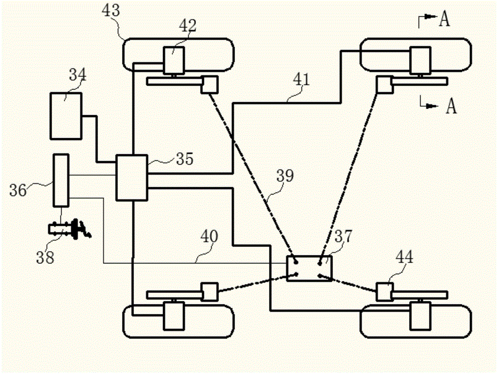
[0026] The structure and working principle of the electro-hydraulic composite braking system with retarding braking function involved in the present invention will be described in detail below in conjunction with the accompanying drawings.

[0027] The electro-hydraulic composite braking system with retarding braking function includes a hydraulic braking subsystem, a motor braking subsystem and a control subsystem. The hydraulic brake subsystem consists of a hydraulic regulator 37 , an electronic brake pedal 38 , a brake pipeline 39 and a double disc brake 44 . The motor braking subsystem consists of a power battery 34 , a DC / AC converter 35 , a power line 41 and a motor 42 ; the control subsystem includes an electronic control unit 36 ​​and a signal line 40 .

[0028] Such as figure 1As shown, the oil tank 1 is connected to the liquid inlet of the high-pressure pump 4 through the check valve 2, the liquid outlet of the high-pressure pump 4 is connected to the liquid outlet o...


PUM


Abstract

The invention discloses an electro-hydraulic combined braking system with a retardance braking function. The electro-hydraulic combined braking system comprises a hydraulic braking subsystem, a motor braking subsystem and a control subsystem. The hydraulic braking subsystem is composed of a hydraulic regulator, an electronic braking pedal, a braking line and a double-disc brake. The motor braking subsystem is composed of a power battery, a DC / AC converter, a power line and a motor. The control subsystem comprises an electronic control unit and a signal line. The electro-hydraulic combined braking system with the retardance braking function can provide three braking modes, namely, the motor braking mode, the retardance braking mode and the hydraulic braking mode; under the condition that the maximum braking torque output in motor braking is limited by the performance of the power battery, the retardance braking mode is used for replacing the motor braking mode to meet the braking requirement of a driver, so that the use frequency of the hydraulic braking mode is effectively reduced, and braking dust pollution and braking noise pollution are effectively reduced.

Description

technical field [0001] The invention relates to the field of brake-by-wire of new energy vehicles, and relates to an electro-hydraulic composite brake system with a retarding brake function and a control method thereof. Background technique [0002] Electric vehicles have the advantages of energy saving and environmental protection, and have become an important development direction of the automotive industry in the future. The difference between electric vehicles and traditional vehicles is the electrification of the drive system and the introduction of regenerative braking in the braking system, which improves the energy utilization efficiency by 60% compared with traditional vehicles, and a large part of the energy comes from the regenerative braking system. Regenerative braking and hydraulic braking together form the electro-hydraulic composite braking system of electric vehicles. The braking energy is recovered by driving the motor to brake, and regenerative braking fo...

Claims


Application Information

Patent Timeline
Patent Type & Authority Applications(China)
IPC IPC(8): B60L7/26B60T13/66
CPCY02T10/72
Inventor 衣丰艳周稼铭陈德阳张竹林周长峰刘永辉吕志明
Owner SHANDONG JIAOTONG UNIV
Learn More