
Equipment for processing valve

A valve and equipment technology, applied in the field of valve processing equipment, can solve problems such as flange edge bending downward, not being able to adapt to the valve, and affecting processing accuracy, so as to ensure flatness, improve drilling efficiency, and high processing accuracy Effect

Active Publication Date: 2015-08-12
EAST CHINA MINING EQUIP CO LTD
View PDF7 Cites 17 Cited by
  • Summary
  • Abstract
  • Description
  • Claims
  • Application Information

AI Technical Summary

Problems solved by technology

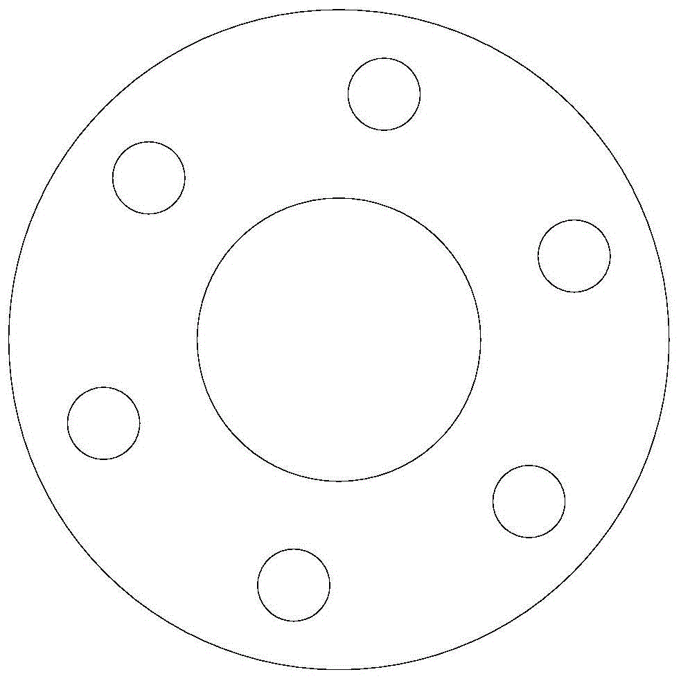
[0005] like figure 1 , 2 As shown, the main structure of the valve is mostly cylindrical, and both ends of the valve are provided with annular flanges. On the edge of the flange, there are 6 threaded holes for connecting external pipes. The connection of these threaded holes is formed into six edge shape, etc.; the existing technology cannot adapt to valves of different sizes when drilling holes, and the fixture needs to be replaced constantly, and sometimes a process hole needs to be processed for positioning; this affects the processing accuracy
Moreover, when the flange is drilled, it is easy to cause the edge of the flange to bend downwards, and severe fractures will occur.

Method used


Image

  • Equipment for processing valve
  • Equipment for processing valve
  • Equipment for processing valve

Examples


Embodiment Construction

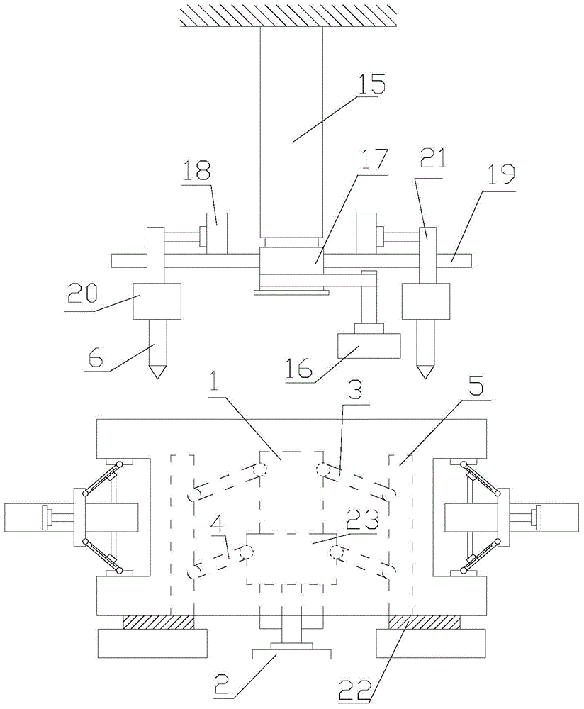
[0034] refer to figure 1 , 2 , 3, 4:

[0035] A device for processing valves proposed by the present invention includes a drilling mechanism for drilling flanges on the valve and a clamping mechanism for clamping the valve;

[0036] The clamping mechanism includes a clamping column 1 and a hydraulic cylinder 2, the clamping column 1 is provided with a first collar 23, and N clamping units are provided along the axial direction of the clamping column 1, N≥2, when N= When 2, the two clamping units are arranged symmetrically with respect to the clamping column 1; when N>2, the clamping units are evenly distributed around the clamping column 1;

[0037] The clamping unit includes a first connecting rod 3, a second connecting rod 4, and a clamping plate 5 for fitting the inner surface of the valve. One end of the first connecting rod 3 is hinged to one end of the clamping plate 5, and the other end is connected to the clamping plate 5. The clamping column 1 is hinged; one end of...


PUM


Abstract

The invention discloses equipment for processing a valve. The equipment comprises a hole drilling mechanism and a clamping mechanism, wherein the clamping mechanism comprises a clamping post and a hydraulic cylinder; a first sleeve ring is arranged on the clamping post; N clamping units are arranged along the axial direction of the clamping post; each clamping unit comprises a first connecting rod, a second connecting rod and a clamping plate used for being attached to the inner surface of the valve; one end of each first connecting rod is hinged to one end of the corresponding clamping plate, and the other end of each first connecting rod is hinged to the clamping post; one end of each second connecting rod is hinged to one end, far away from the first connecting rod, of the corresponding clamping plate, and the other end of each second connecting rod is hinged to the first sleeve ring; the first sleeve ring is in transmission connection with the hydraulic cylinder; the hole drilling mechanism comprises a drill bit; the drilling direction of the drill bit is parallel to the axial direction of the clamping post. The equipment has the advantages that the clamping plate can be used for clamping the valves with different diameters; the applicability and the processing precision are high; the support mechanism is designed, and is used for supporting the edge of a flange, and the sealing performance when the flange is connected with an external pipeline is ensured.

Description

technical field [0001] The invention relates to the technical field of mining equipment, in particular to equipment for processing valves. Background technique [0002] A valve is a device used to control the direction, pressure, and flow of a fluid in a fluid system. It is a device that makes or stops the medium in the piping and equipment and controls its flow. [0003] The valve is a control component in the pipeline fluid delivery system. It is used to change the passage section and the flow direction of the medium, and has the functions of diversion, cut-off, throttling, check, diversion or overflow relief. Valves used for fluid control range from the simplest shut-off valve to various valves used in extremely complex automatic control systems. Valves for industrial pipelines. It can be used to control the flow of various types of fluids such as water, steam, oil, gas, mud, various corrosive media, liquid metals and radioactive fluids. The working pressure of the valv...

Claims


Application Information

Patent Timeline
Patent Type & Authority Applications(China)
IPC IPC(8): B23B41/00B23Q3/08
CPCB23B41/00B23Q3/062B23Q3/08B23Q3/082B23Q2703/04
Inventor 倪建平闻斌楠王剑飞
Owner EAST CHINA MINING EQUIP CO LTD
Learn More