
Abrasive belt machine

An abrasive belt machine and abrasive belt technology, applied in the field of abrasive belt machines, can solve problems such as easily damaged workpieces, difficult to achieve grinding effects, unsuitable for precision grinding, curved surface grinding, etc., and achieve the effect of ensuring balance

Active Publication Date: 2015-08-05
SHANGHAI DIJIA MACHINERY EQUIP CO LTD
View PDF9 Cites 10 Cited by
  • Summary
  • Abstract
  • Description
  • Claims
  • Application Information

AI Technical Summary

Problems solved by technology

[0004] 1. Unable to control the constant tension of the contact wheel pressure and abrasive belt tension;
[0005] 2. The contact wheel and the abrasive belt use springs to control the tension. The spring tension is difficult to maintain constant tension, and the force will be changed by the size of the external force. The greater the compression force, the greater the rebound force, which is easy to damage the workpiece;
[0006] 3. No dust collection device, the dust generated will pollute the environment
[0007] 4. Adopt ordinary motor drive, when the resistance of the abrasive belt increases, the motor will change the linear speed of the abrasive belt due to the change of resistance, and it is difficult to achieve the ideal grinding effect when the surface of the polished part is uneven;
[0008] 5. Not suitable for precision grinding and surface grinding

Method used

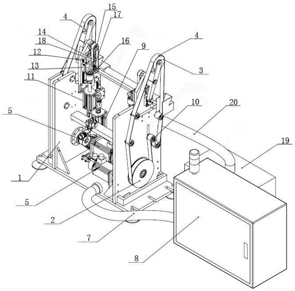

Image

  • Abrasive belt machine

Examples


Embodiment Construction

[0029] In order to deepen the understanding of the present invention, the present invention will be further described in detail below in conjunction with the accompanying drawings and embodiments. The following examples are only used to illustrate the technical solution of the present invention more clearly, but not to limit the protection scope of the present invention.

[0030] like figure 1 As shown, the abrasive belt machine includes a frame 1 and a driving wheel 2 symmetrically arranged on the frame 1, a contact wheel 3, an abrasive belt 4 and a servo motor 5, and the servo motor 5 is connected with the driving wheel 2 to drive the driving wheel to run; The contact wheel 3 is installed on the frame through the contact wheel arm 6, the abrasive belt 4 is sleeved on the driving wheel 2 and the contact wheel 3, the driving wheel 2 drives the contact wheel 3 to run, and the contact wheel 3 drives the abrasive belt 4 to run; the abrasive belt 4 A belt tension control mechanis...


PUM


Abstract

The invention discloses an abrasive belt machine. The abrasive belt machine comprises a frame, driving wheels, contact wheels, abrasive belts and servo motors; the driving wheels, the contact wheels, the abrasive belts and the servo motors are symmetrically arranged on the frame; each servo motor is connected with the corresponding driving wheel; each abrasive belt is arranged on the corresponding driving wheel and contact wheel in a sleeving mode; each contact wheel is driven by the corresponding driving wheel to run; each abrasive belt is driven by the corresponding contact wheel to run; one side of each contact wheel is provided with a contact wheel pressure control mechanism; one side of each abrasive belt is provided with an abrasive belt tension control mechanism; one side of the abrasive belt machine is connected with a PLC (Programmable Logic Controller) control box. According to the abrasive belt machine, the double-head double contact wheels can be rapidly replaced or automatically switched for different curved surfaces during use conveniently; the abrasive belt tension control mechanisms are controlled by a precision pressure reducing valve, the tension of the abrasive belts can be automatically adjusted when the resistance is produced so as to enable the tension to be stabilized within a set value, and accordingly the smooth operation of the abrasive belts is ensured and the service life of the abrasive belts is extended; the abrasive belt machine is provided with the contact wheel pressure control mechanisms, the contact wheels are rubber coating wheels, and accordingly the full contact of the complex curved surfaces can be implemented during polishing, the elasticity is achieved, and workpieces are not easy to damage.

Description

technical field [0001] The invention relates to an abrasive belt machine for grinding workpieces, in particular to an abrasive belt machine. Background technique [0002] Abrasive belt machines are ideal production tools for metal processing, machinery manufacturing, stamping casting, molds, plastics, precision parts, and handicraft industries, such as surface grinding and chamfering, deburring, and other products. Angle, edging, rounding, polishing and other operations, but when the existing belt sander is working, the motor heats up seriously, and the heat dissipation effect is poor, which affects the service life of the belt sander. [0003] The structure of the existing double-head abrasive belt machine is that two sets of abrasive belt grinding devices are arranged symmetrically on the machine base. Wherein the active abrasive belt wheel is connected with the transmission mechanism, and the transmission mechanism drives the active abrasive belt wheel to rotate, and the...

Claims


Application Information

Patent Timeline
IPC IPC(8): B24B21/12B24B21/18B24B21/20B24B55/08
CPCB24B21/12B24B21/18B24B21/20B24B55/08
Inventor 孙理军张传海
Owner SHANGHAI DIJIA MACHINERY EQUIP CO LTD
Learn More