In-hole dual-frequency ground penetrating radar antenna

A technology of ground penetrating radar and antenna, which is applied to antennas, devices that make the antennas work in different frequency bands at the same time, and electromagnetic wave detection. The effect of easy R&D improvement, few processing steps and high resolution

Active Publication Date: 2015-07-29
TONGJI UNIV
View PDF3 Cites 2 Cited by
  • Summary
  • Abstract
  • Description
  • Claims
  • Application Information

AI Technical Summary

Problems solved by technology

[0006] 3. Antenna size
[0007] The Chinese patent whose patent No. is CN102354794B discloses a kind of omnidirectional cylindrical dipole antenna for underground geological exploration mine. The monopole antenna composed of the loading resistance between the antenna sections and in the seat holes at both ends of the antenna sections and the corresponding pressure spring, the intersegment fixing sleeve, the support tube, the nut sleeve, the connection fixing sleeve, the coaxial cable, the The center frequency of the antenna is only 100MHz, and the frequency cannot be converted, which limits the detection range. The structure is complex, the cost is high, and the volume is large. It can only be applied to the underground and not to the foundation pit enclosure structure.

Method used


Image

  • In-hole dual-frequency ground penetrating radar antenna
  • In-hole dual-frequency ground penetrating radar antenna
  • In-hole dual-frequency ground penetrating radar antenna

Examples


Embodiment 1

[0035] Such as figure 1 As shown, a dual-frequency ground-penetrating radar antenna in a hole is set in the reserved hole of the foundation pit enclosure structure to detect the disease of the foundation pit enclosure structure, including casing 6, pipe bottom sealing block 8, pipe The top sealing block 9, the coaxial cable 5, and the top antenna pole and the bottom antenna pole that are relatively arranged inside the casing 6, each antenna pole includes a conical antenna head 1, a first antenna section 2, The head of the coaxial cable 5 is connected to the conical antenna head 1 of each antenna pole, and the tail is connected to the sealing block 9 on the pipe top.

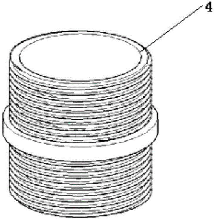
[0036] The outer edge of the frequency conversion joint 4 is provided with external threads, and the first antenna section 2 and the second antenna section 3 are respectively provided with internal threads. There is also a snap ring on the outer edge of the joint 4, the conical antenna head 1, the first antenna ...

Embodiment 2

[0043] When the frequency conversion connector 4 is an acrylic connector group, the working center frequency is 500MHz. The acrylic connector group includes separate acrylic connectors and integral acrylic connectors. The integral acrylic connector is set in the bottom antenna pole, and the separated acrylic connector is set in the top antenna. In the pole, the remaining parts in this embodiment are the same as in Embodiment 1.

[0044] Such as Figure 5 As shown, the figure shows the return loss curves under the numerical simulation conditions when copper frequency conversion joints and acrylic frequency conversion joints are used respectively. The center frequencies are 270MHz and 500Mhz, and the return loss values ​​​​respectively reach -23dB and -25dB. The antenna has better working performance near these two frequencies.

[0045] Table 1 is the data comparison between the ground penetrating radar antenna of the present invention and the common radar antenna. It can be se...


PUM


Abstract

The invention relates to an in-hole dual-frequency ground penetrating radar antenna, which is arranged in a reserved hole of a foundation pit support structure for detecting diseases of the foundation pit support structure. The in-hole dual-frequency ground penetrating radar antenna comprises a casing, a casing bottom sealing block, a casing top sealing block, a coaxial cable, and a top antenna polaron and a bottom antenna polaron arranged inside the casing oppositely, wherein each antenna polaron comprises a conical antenna head, a first antenna joint, a variable frequency joint and a second antenna joint connected sequentially; the head part of the coaxial cable is respectively connected with the conical antenna head of each antenna polaron, and the tail is connected with the casing top sealing block. Compared with the prior art, the in-hole dual-frequency ground penetrating radar antenna has the advantages of high central frequency, high resolution, small size, simple operation, variable operation, high material strength, light weight, simple manufacturing and processing, low cost and the like.

Description

technical field [0001] The invention relates to a radar antenna, in particular to a dual-frequency ground-penetrating radar antenna in a hole. Background technique [0002] In recent years, the in-depth development of urban functions has gradually shifted to the large-scale and in-depth development and utilization of underground spaces, such as rail transit hub stations, major projects across rivers, and underground spaces of high-rise buildings. In the construction of underground engineering, the enclosure structure of foundation pit is the key carrier to ensure the safety and environmental safety of underground engineering. Unforeseen unfavorable factors will affect the quality of the foundation pit enclosure structure to a large extent. The enclosure structure often has serious quality defects such as voids, mud inclusions, cracks, segregation, and insufficient length of the enclosure structure, resulting in water leakage, quicksand, support cracking, and even water and ...

Claims


Application Information

Patent Timeline
Patent Type & Authority Applications(China)
IPC IPC(8): H01Q13/08H01Q5/20G01V3/12
Inventor 谢雄耀覃晖姚荣杰洪概
Owner TONGJI UNIV
Why Eureka
Try Eureka