Small differential tee band-pass filter
A filter and differential technology, applied in the field of microwave communication, can solve the problems of difficult independent control bandwidth, narrow common-mode rejection bandwidth, and low suppression level, and achieve good in-band return loss, small size, and obvious suppression Effect
- Summary
- Abstract
- Description
- Claims
- Application Information
AI Technical Summary
Problems solved by technology
Method used
Image
Examples
Embodiment 1
[0028] Differential multi-frequency filters can cover multiple communication standards and effectively suppress common-mode noise, and are increasingly used in modern communication systems. Not only can it be used independently, but it can also be integrated in the front end of the radio frequency system for filtering.
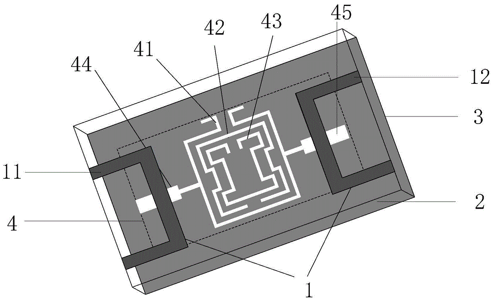
[0029] refer to figure 1 , the present invention is a miniaturized differential three-pass filter, including a microstrip feeder 1, a microstrip dielectric substrate 2, a metal ground plate 3, and a defective ground structure 4, wherein:
[0030] The microstrip dielectric substrate 2 adopts a copper-clad dielectric substrate with a dielectric constant of 2.2 and a thickness of 0.787mm, and its size is 30mm×48.4mm. The upper surface is symmetrically provided with a microstrip feeder 1 with respect to the longitudinal axis; the microstrip feeder 1 includes two U-shaped differential input ports 11 and differential output ports 12 on the same side, and the ports ...
Embodiment 2
[0035] The overall composition of the miniaturized differential three-pass band-pass filter is the same as in Embodiment 1, and different structural parameters are provided below:
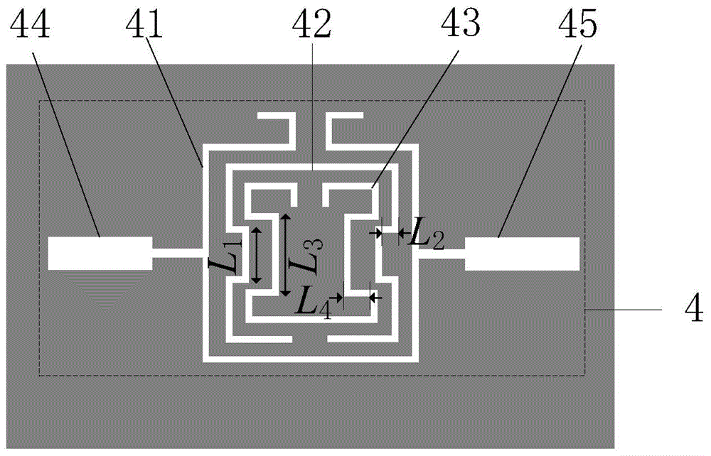
[0036] refer to figure 2 , the openings of the outermost complementary split resonant ring 41 and the innermost complementary split resonant ring 43 are provided with mouth edge extensions, and the extensions are provided for the convenience of controlling the center frequencies of the three passbands. The mouth edge extension section of the outermost complementary split resonant ring 41 is located outside the split ring, and the line length is 2.7 mm, which are respectively bent to both sides. The mouth edge extension section of the innermost complementary split resonator ring 43 is located inside the split ring, and the line length is The length is 0.6 mm.
[0037] The wiring on the left and right sides of the complementary split resonant ring 42 in the middle layer and the complementary split ...
Embodiment 3
[0042] The overall composition of the miniaturized differential three-pass band-pass filter is the same as in Embodiment 1-2, and different structural parameters are given below:
[0043] The innermost complementary split resonant ring 43 opens downward, the middle complementary split resonator 42 opens upward, and the outermost complementary split resonant ring 41 opens downward.
PUM
| Property | Measurement | Unit |
|---|---|---|
| Thickness | aaaaa | aaaaa |
| Line width | aaaaa | aaaaa |
| Line width | aaaaa | aaaaa |
Abstract
Description
Claims
Application Information
 - Generate Ideas
- Intellectual Property
- Life Sciences
- Materials
- Tech Scout
- Unparalleled Data Quality
- Higher Quality Content
- 60% Fewer Hallucinations
Browse by: Latest US Patents, China's latest patents, Technical Efficacy Thesaurus, Application Domain, Technology Topic, Popular Technical Reports.
© 2025 PatSnap. All rights reserved.Legal|Privacy policy|Modern Slavery Act Transparency Statement|Sitemap|About US| Contact US: help@patsnap.com


