
A needle bar equipped with a shock absorber

A vibration absorber and needle bar technology, which is applied to sewing equipment, needle seats for sewing machines, textiles and papermaking, etc. It can solve problems such as sewing machine failures and increased wear of moving rods

Inactive Publication Date: 2017-04-05
WUJIANG WANGONG ELECTROMECHANICAL EQUIP
View PDF3 Cites 0 Cited by
  • Summary
  • Abstract
  • Description
  • Claims
  • Application Information

AI Technical Summary

Problems solved by technology

The trend of high-speed development of modern industrial sewing machines is clear, and the continuous increase in speed has caused increased wear and tear on the moving rods of the various mechanisms of the sewing machine, resulting in more failures of the sewing machine

Method used


Image

  • A needle bar equipped with a shock absorber
  • A needle bar equipped with a shock absorber
  • A needle bar equipped with a shock absorber

Examples


Embodiment 1

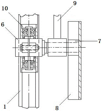
[0033] see figure 2 As shown, the vibration absorber is a built-in vibration absorber 10 , which is placed in the inner cavity of the cylinder of the needle bar 1 , and its height is located on the axis line of the slider pin 6 . The cheap vibration of needle bar 1 is bending vibration, drives needle bar 1 to move through connecting rod 9, slide block pin 6, and the axis line of slide block pin 6 is that needle bar 1 bends the most at the place near.

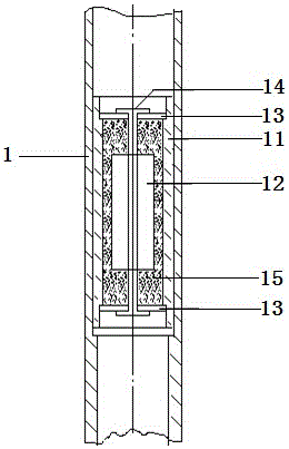
[0034] Further, see image 3 As shown, the built-in vibration absorber 10 includes a vibration absorber tube body 11, a cylindrical mass 12 is arranged inside the vibration absorber tube body 11, and a circular spacer is provided at the upper and lower ends of the vibration absorber tube body 11. Pad 13, the cylindrical mass 12 is fixed between the upper and lower circular spacers 13 by copper leaf springs 14, the inner wall of the vibration absorber tube body 11 and the upper and lower circular spacers The shaped spacer 13 f...

Embodiment 2

[0038] see Figure 5 As shown, the shock absorber is an external shock absorber 17, which is tightly sleeved on the outer wall of the cylinder of the needle bar 1 and installed on the mounting pad 23 on the outer wall of the cylinder of the needle bar 1. The needle bar 1 The outer diameter of the cylinder is 8 mm, the height of the external vibration absorber 17 is located below the slider pin 6, and the upper plane of the external vibration absorber 17 is 5 mm away from the axis line of the slider pin 6. -10 mm.

[0039] Further, the external vibration absorber 17 includes a vibration absorber outer tube 18 and a vibration absorber inner tube 19, an annular mass 20 is arranged between the vibration absorber outer tube 18 and the vibration absorber inner tube 19, the An annular spacer 21 is arranged on the upper and lower ends of the outer tube 18 of the vibration absorber and the inner tube 19 of the vibration absorber, and the annular mass 20 is fixed on the upper and lower...


PUM


Abstract

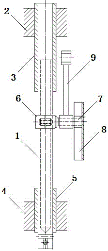
The invention discloses a needle bar equipped with a vibration absorber. The needle bar comprises a needle bar, wherein the upper part of the needle bar is nested in an upper sleeve of the top of a lathe head, the lower part of the needle bar is nested in a lower sleeve of the bottom of the lathe head, the needle bar is in movable fit with the upper and lower sleeves and can slide up and down in the upper and lower sleeves, a slider pin is arranged at the middle part of the needle bar and is connected with a slider, the slider is arranged in a sliding groove, a connecting rod is arranged at the joint of the slider pin and the slider and is connected with an upper shaft of a sewing machine through a crank, the upper shaft of the sewing machine drives the crank to rotate, the crank drives the connecting rod to do planar motion, the connecting rod drives the slider and the needle bar to do up-and-down reciprocating motion, and the vibration absorber is arranged on the needle bar. According to the needle bar disclosed by the invention, the vibration absorber is mounted at a maximum-bending position of the needle bar and contains an additional mass, the additional mass moves along with the needle bar and generates motion damping, bending energy of the needle bar is absorbed by a damping material in the vibration absorber, and steepness of bending vibration peaks is reduced by the motion damping, so that the dynamic working conditions of the needle bar are improved.

Description

technical field [0001] The invention relates to a needle bar applied to a material threading mechanism of a template sewing machine, in particular to a needle bar equipped with a vibration absorber. Background technique [0002] The stabbing mechanism is the main source of vibration and noise of the template sewing machine. The trend of high-speed development of modern industrial sewing machines is clear, and the continuous increase in speed has caused increased wear and tear on the moving rods of the various mechanisms of the sewing machine, resulting in more failures of the sewing machine. In the stabbing mechanism of the sewing machine, the needle bar reciprocates, and the moving needle bar vibrates greatly in the lateral direction. [0003] The stabbing mechanism is installed between the upper shaft and the needle bar of the template sewing machine. The needle bar is the motion output part of the stabbing mechanism. The mechanism converts the rotary motion of the upper ...

Claims


Application Information

Patent Timeline
Patent Type & Authority Patents(China)
IPC IPC(8): D05B55/10
Inventor 周玉峰祝章琛
Owner WUJIANG WANGONG ELECTROMECHANICAL EQUIP
Learn More