Elevator device
A technology for elevators and cars, applied in the field of elevator devices with an air rectification structure, can solve the problems of increasing the overall weight of the car, increasing the load of the elevator device, and manufacturing costs, and achieves light weight, simple structure, and reduced wind resistance and noise Effect
- Summary
- Abstract
- Description
- Claims
- Application Information
AI Technical Summary
Problems solved by technology
Method used
Image
Examples
no. 1 Embodiment
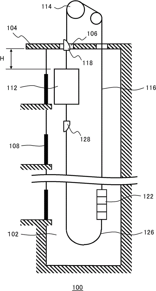
[0031] figure 1It is a schematic diagram illustrating the elevator apparatus 100 according to the first embodiment of the present invention. The elevator device 100 includes a hoistway 102 , a car 112 , a traction machine, a traction rope 116 , a diversion component 118 , a counterweight 122 , a compensation rope 126 and a diversion component 128 .
[0032] The hoistway 102 provides space for the car 112 to move up and down. The traction machine drives the traction rope 116 through the traction wheel 114 . The car 112 and the counterweight 122 are connected to both ends of the traction rope 116 , and are raised and lowered in the hoistway 102 under the traction of the traction rope 116 . The hoistway 102 is provided with a landing door 108 at a position corresponding to each landing.
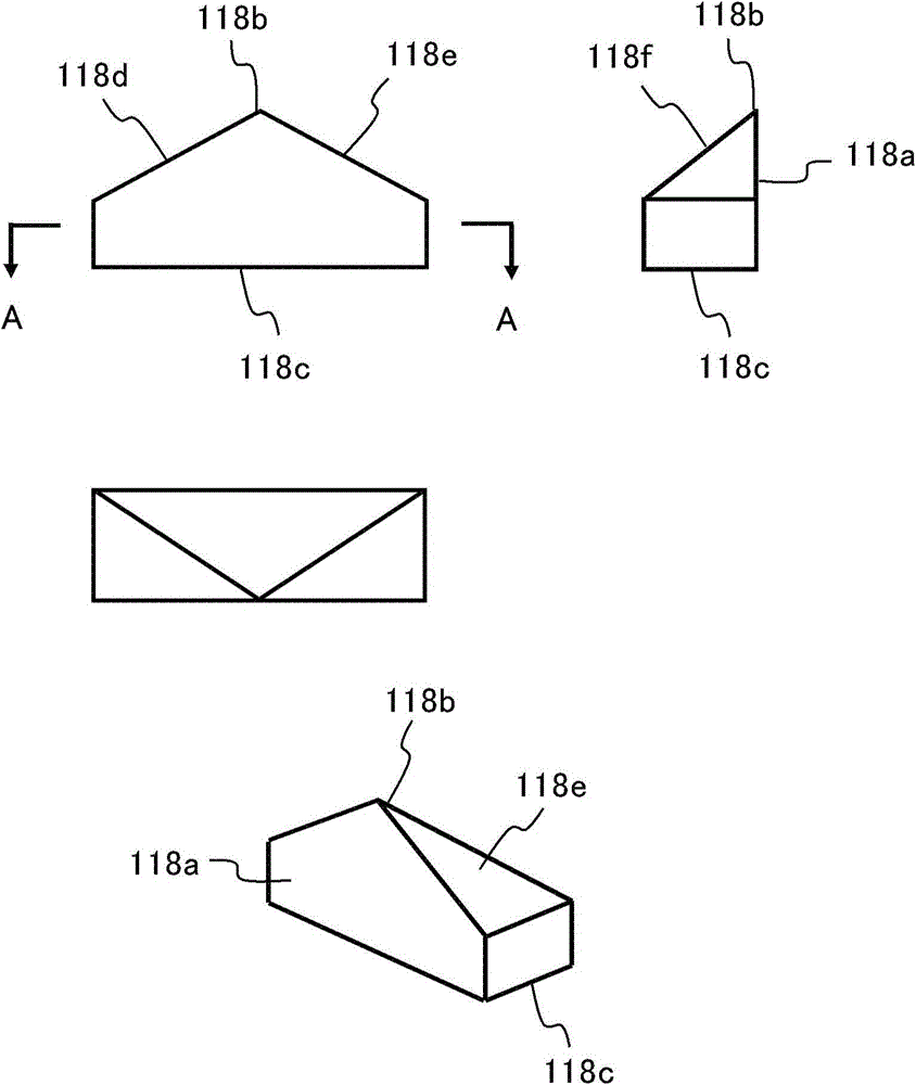
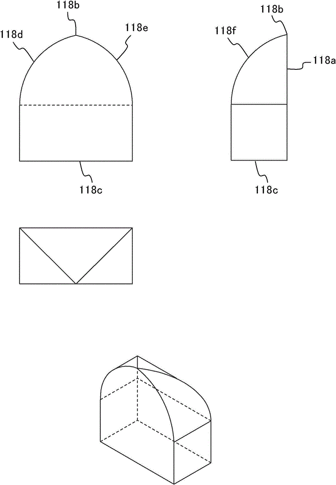
[0033] exist figure 1 In , the traction machine is simply represented by the traction wheel 114 instead, and the traction machine is arranged in the machine room above the hoistway 102 . Th...
no. 2 Embodiment
[0063] Figure 10 It is a schematic diagram of the elevator apparatus of the second embodiment provided with the vibration damping device. The elevator device of this embodiment is figure 1 A modified example of the elevator apparatus 100 of the first embodiment is shown. Compared with the first embodiment, the elevator apparatus of this embodiment is provided with a vibration damping device 1002 additionally. Except for this feature, other parts are basically the same as the elevator installation 100 . That is, the elevator device of the present embodiment also includes figure 1 The hoistway 102, the car 112, the traction machine, the traction rope 116, the diversion member 118, the counterweight 122, the compensation rope 126 and the diversion member 128 are shown, and these components are the same as those of the first embodiment. same function. so, Figure 10 Only the structures around the vibration damping device 1002 are briefly shown, and only the technical featur...
no. 3 Embodiment
[0072] Figure 11 It is a schematic diagram of the elevator apparatus of the third embodiment provided with a fairing. The elevator device of this embodiment is figure 1 A modified example of the elevator apparatus 100 of the first embodiment is shown. Compared with the first embodiment, the elevator apparatus of this embodiment is provided with an upper fairing 1102 and a lower fairing 1104 additionally. Except for these features, other parts are basically the same as the elevator device 100 . That is, the elevator device of the present embodiment also includes figure 1 The hoistway 102, the car 112, the traction machine, the traction rope 116, the diversion member 118, the counterweight 122, the compensation rope 126 and the diversion member 128 are shown, and these components are the same as those of the first embodiment. same function. so, Figure 10 Only the structure around the car 112 is briefly shown, and only the technical features different from the first embod...
PUM
 Abstract
Description
Claims
Application Information
 - R&D
- Intellectual Property
- Life Sciences
- Materials
- Tech Scout
- Unparalleled Data Quality
- Higher Quality Content
- 60% Fewer Hallucinations
Browse by: Latest US Patents, China's latest patents, Technical Efficacy Thesaurus, Application Domain, Technology Topic, Popular Technical Reports.
© 2025 PatSnap. All rights reserved.Legal|Privacy policy|Modern Slavery Act Transparency Statement|Sitemap|About US| Contact US: help@patsnap.com


