Synchronization information sending method, synchronization information detection method and user equipment

A technology for synchronizing information and sending equipment, applied in the direction of synchronization devices, wireless communications, electrical components, etc., can solve problems such as not knowing the resources found in neighboring cells, no solution, and not synchronous transmission

Active Publication Date: 2015-07-22
DATANG MOBILE COMM EQUIP CO LTD
View PDF4 Cites 19 Cited by
  • Summary
  • Abstract
  • Description
  • Claims
  • Application Information

AI Technical Summary

Problems solved by technology

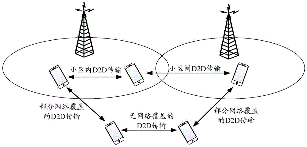
[0007] 2. For the scenario of D2D transmission between cells, since the two cells may be out of sync, if the UEs are synchronized with the network side, the two UEs may be out of sync and cannot directly perform D2D discovery or In D2D communication, the UE may not know the discovery resources used by neighboring cells
[0008] 3. For some network coverage scenarios, UEs outside the coverage area and UEs in the coverage area do not transmit synchronously, which may cause serious mutual interference
However, there is no corresponding solution for how UE sends and designs synchronization channels so that different UEs can use synchronization channels to transmit different types of information

Method used


Image

  • Synchronization information sending method, synchronization information detection method and user equipment
  • Synchronization information sending method, synchronization information detection method and user equipment
  • Synchronization information sending method, synchronization information detection method and user equipment

Examples


Embodiment 1

[0318] Embodiment 1. It is assumed that both UE1 and UE2 are within network coverage and belong to different synchronous cells; UE3 and UE4 are outside network coverage. Among them, UE1, UE2, and UE3 send synchronization signals, and UE4 receives synchronization signals. For details, see Figure 5 shown.

[0319] 1. UE1-UE3 respectively send synchronization signals on agreed physical resources according to the synchronization reference obtained from the reference synchronization source.

[0320] Specifically, UE1 and UE2 obtain synchronization references from downlink synchronization signals of cell 1 and cell 2 respectively; UE3 obtains synchronization references from GPS.

[0321] 2. UE1-UE3 determine whether to send synchronization information on the synchronization channel corresponding to the synchronization signal according to their own network connection status and / or reference synchronization source information, and determine whether to send synchronization informatio...

Embodiment 2

[0329] Embodiment 2, it is assumed that UE1 is within network coverage and belongs to cell 1; UE2, UE3, and UE4 are outside network coverage. Among them, UE1, UE2, and UE3 send synchronization signals, and UE4 receives synchronization signals. For details, see Figure 6 shown.

[0330] 1. UE1-UE3 respectively send synchronization signals on agreed physical resources according to the synchronization reference obtained from the reference synchronization source.

[0331] Specifically, UE1 and UE2 obtain the synchronization reference from cell 1 and cell 2 respectively; UE3 obtains the synchronization reference from the cluster head UE. Generally, in the case of no network, there will be a cluster head in a mutually adjacent cluster to send a synchronization signal, so that the surrounding UEs can obtain mutual synchronization by synchronizing with it, and then perform D2D transmission.

[0332] 2. UE1-UE3 determine the synchronization information carried by the synchronization ...


PUM


Abstract

Disclosed in the present application are a method for sending and detecting synchronisation information, and a user device. The method comprises: a sending device sends a synchronisation signal, and on the basis of its own network connection state and / or reference synchronisation source information, determines whether to send synchronisation information on a synchronisation channel corresponding to the synchronisation signal; if determining to send synchronisation information on the synchronisation channel, then the sending device, on the basis of its own network connection state and / or reference synchronisation source information, determines the synchronisation information that needs to be sent on the synchronisation channel and, on appointed physical resources, sends the determined synchronisation information by means of the synchronisation channel. The present application provides a solution for sending synchronisation information in a D2D application scenario; the sending device can, on the basis of its own network connection state and / or reference synchronisation source information, determine whether to send synchronisation information on a synchronisation channel corresponding to a synchronisation signal, and the synchronisation information carried in a synchronisation channel can transfer between user devices the synchronisation information thereof, expanding the scope of synchronisation.

Description

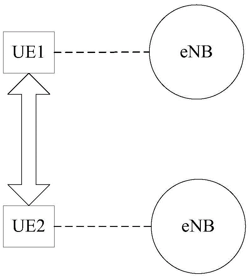
technical field [0001] The invention relates to the technical field of wireless communication, in particular to a method for sending and detecting synchronization information and user equipment. Background technique [0002] Device-to-Device (D2D), that is, terminal direct technology, means that adjacent user equipment (User Equipment, UE; also known as terminal) can transmit data through a direct link within a short distance. It does not need to be forwarded through the central node (ie base station), see figure 1 shown. [0003] Long Term Evolution (LTE) D2D technology refers to the D2D discovery and communication process that works on the licensed frequency band of the LTE network and is controlled by the LTE network. The LTE D2D technology can not only give full play to the advantages of the D2D technology, but also overcome some problems of the traditional D2D technology due to the control of the LTE network, such as problems such as uncontrollable interference. The ...

Claims


Application Information

Patent Timeline
Patent Type & Authority Applications(China)
IPC IPC(8): H04L27/26H04W24/02
CPCH04W56/001H04W56/002
Inventor 陈文洪赵锐高秋彬彭莹
Owner DATANG MOBILE COMM EQUIP CO LTD
Why Eureka
Try Eureka