Connecting member and combined connector thereof
A technology for connecting components and connecting heads, which is applied in the direction of connection, conductive connection, connection contact material, etc.
- Summary
- Abstract
- Description
- Claims
- Application Information
AI Technical Summary
Problems solved by technology
Method used
Image

Examples
Embodiment approach 1
[0027] Implementation Mode 1: For detailed structure, see Figure 4 . This is a wall bushing used for thin walls, and it is also used indoors, such as electrical cabinets and cable branch boxes. The walls are actually steel plates.
[0028] From Figure 4 It can be seen that the present invention has a conductive connecting body 1, an insulator 2, and a mounting part 4, and the connectors at both ends of the conductive connecting body 1 are internally threaded connectors, and the internally threaded joints at both ends are through. The installation part 4 is fixed on the insulator 2 or the installation part 4 is integrated with the insulator 2, and the installation part 4 is used for fixing the wall-through pipe sleeve on the wall. The insulator 2 is firmly attached to the outside of the conductive connecting body 1, but its length is longer than that of the conductive connecting body 1, so that the conductive connecting body 1 is hidden in the insulator 2, and the long part...
Embodiment approach 2
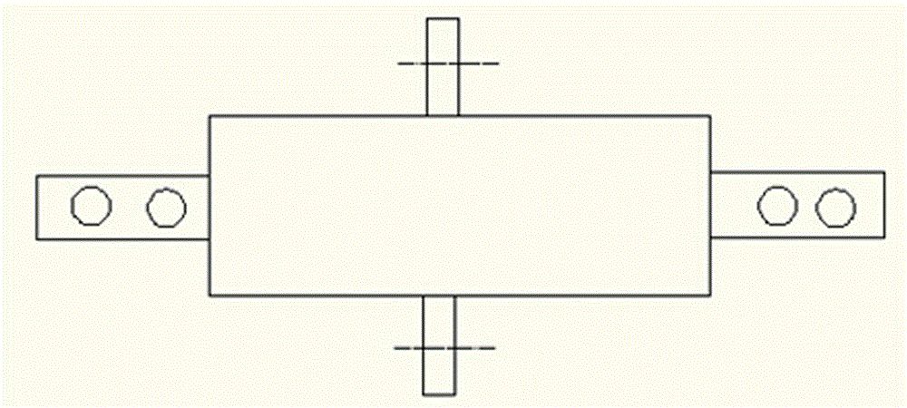
[0031] Embodiment 2: This is a wall-piercing casing for outdoor use.
[0032] From Figure 5 It can be seen that the conductive connecting body 1 of this embodiment adopts a solid round steel structure, with screw holes at both ends, the length of the insulator 2 exceeds the outer ends of the screw holes, and the protruding parts of the insulator 2 are respectively formed at the outer ends of the two screw holes. One end interrupter 5. This structure makes the wall pipe sleeve have sufficient length and strength to adapt to its outdoor working conditions. The insulator is made of synthetic insulating material, and its skirt is used to prevent water accumulation.
Embodiment approach 3
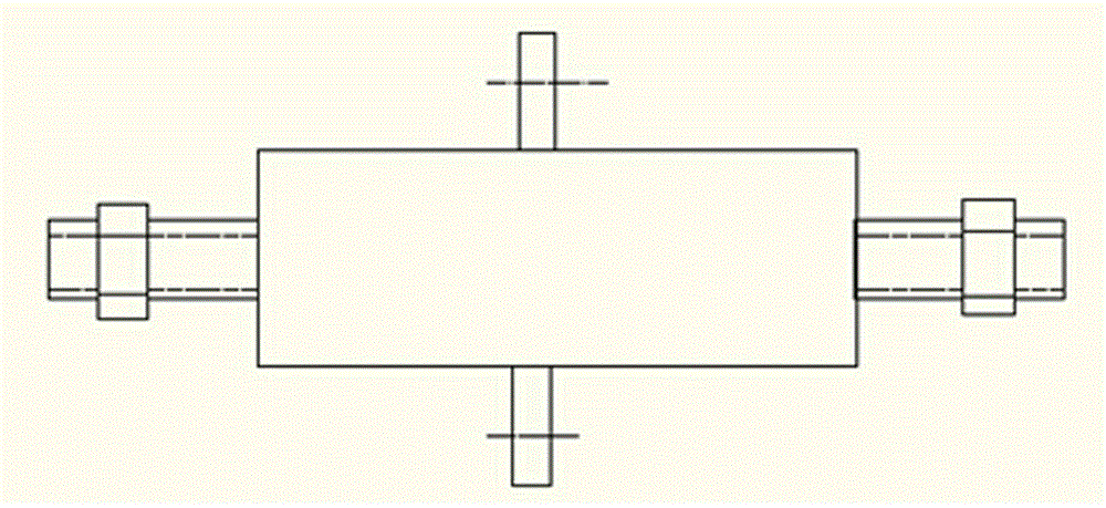
[0033] Embodiment 3: This is a wall-piercing sleeve, which has advantages in length and strength, and is very suitable for extra-thick walls.
[0034] From Figure 6 It can be seen that in this embodiment, compared with the embodiment, the connectors at both ends of the conductive connecting body 1 are externally threaded connectors 12, and there is enough space between the insulator 2 and the externally threaded connector 12 to allow the external connectors to be inserted and form Side arc extinguishing chamber 6. In order to further improve the arc extinguishing effect, the length of the insulator 2 exceeds the end face of the externally threaded connector to form an end arc extinguishing chamber 5 .
[0035] This embodiment is suitable for the connected power line terminal is a screw hole interface, and the length of the conductive connecting body 1 can be arbitrarily selected according to the thickness of the wall.
PUM
 Abstract
Description
Claims
Application Information
 - R&D
- Intellectual Property
- Life Sciences
- Materials
- Tech Scout
- Unparalleled Data Quality
- Higher Quality Content
- 60% Fewer Hallucinations
Browse by: Latest US Patents, China's latest patents, Technical Efficacy Thesaurus, Application Domain, Technology Topic, Popular Technical Reports.
© 2025 PatSnap. All rights reserved.Legal|Privacy policy|Modern Slavery Act Transparency Statement|Sitemap|About US| Contact US: help@patsnap.com