
Light transmittance measurement equipment

A technology for measuring equipment and light transmittance, which is applied in the direction of transmittance measurement, etc., can solve the problems of not being suitable for factory batch testing, not considering the influence of ambient light, and insufficient test accuracy, so as to save measurement time and achieve universality Good and easy to replace

Inactive Publication Date: 2015-07-22
TPK TOUCH SOLUTIONS (XIAMEN) INC
View PDF6 Cites 7 Cited by
  • Summary
  • Abstract
  • Description
  • Claims
  • Application Information

AI Technical Summary

Problems solved by technology

[0004] However, the current light transmittance measurement device does not consider the influence of ambient light when measuring, resulting in insufficient test accuracy
In addition, since the small hole on the protective glass needs to measure the light transmittance under two wavelength light sources of green light and near-infrared light, the existing equipment cannot realize the simultaneous measurement of the two light sources in the same hole, but must be measured separately test, not suitable for factory batch test
Furthermore, the existing equipment is all customized, and different products must be re-made, which cannot be used universally, and the mass production efficiency is poor

Method used


Image

  • Light transmittance measurement equipment
  • Light transmittance measurement equipment
  • Light transmittance measurement equipment

Examples


Embodiment Construction

[0028] The present invention will be further described in detail below in conjunction with the accompanying drawings and specific embodiments.

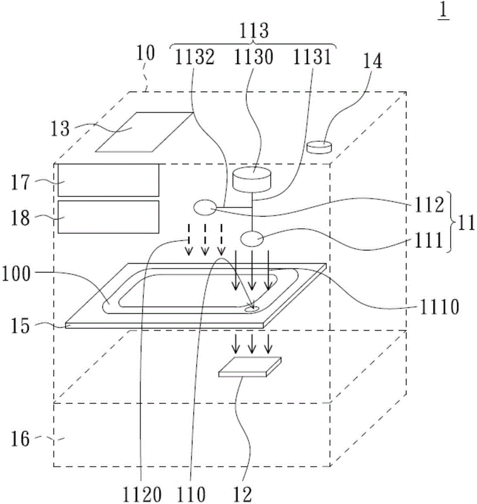
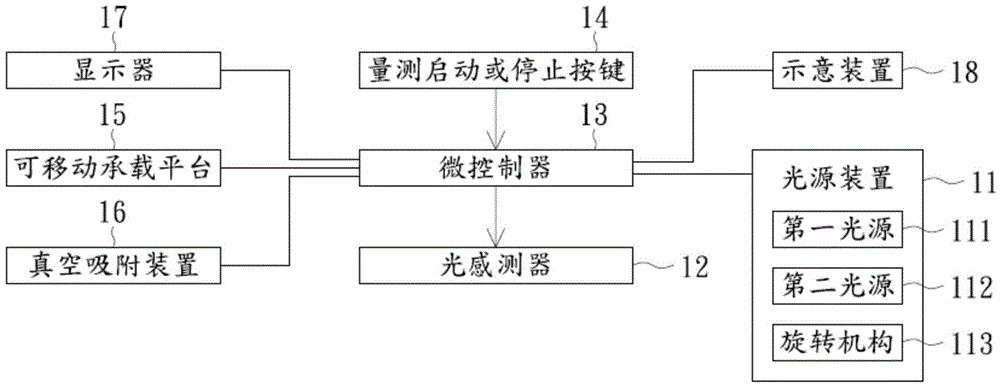
[0029] Please refer to figure 1 and figure 2 , figure 1 It is a schematic structural diagram of the light transmittance measuring device described in one embodiment of the present invention. figure 2 for figure 1 The functional block diagram of the light transmittance measuring device shown. Such as figure 1 and figure 2 As shown, the light transmittance measurement device 1 described in this embodiment is used to measure the light transmittance of the object to be tested, such as the protective glass 100 used on smart phones and tablet computers. , but the present invention is not limited thereto. The cover glass 100 has at least one hole-shaped area 110 , and the light transmittance measurement device 1 described in this embodiment is mainly for measuring the light transmittance of the hole-shaped area 110 on the cover gla...


PUM


Abstract

A light transmittance measuring apparatus includes a housing made of opaque material, a light source device disposed in the housing and for emitting a first light beam and a second light beam to the object, a light sensor and a microcontroller. The first light beam and the second light beam have different wavelength ranges and have a first light intensity value and a second light intensity value, respectively. The light sensor is for sensing the first and second light beams after passing through the object and obtaining a third and fourth light intensity values, respectively. The microcontroller is for comparing the first and third light intensity values to obtain the light transmittance of the object under the first light beam and compare the second and fourth light intensity values to obtain the light transmittance of the object under the second light beam.

Description

technical field [0001] The invention relates to a light transmittance measuring device, in particular to a light penetration measuring device for measuring the light transmittance of an object to be measured. Background technique [0002] Smart phones on the market are equipped with light sensors and proximity sensors. The light sensor can automatically adjust the brightness of the screen, and the distance sensor can sense the distance between the mobile phone and the face during a call, so as to automatically turn off the display of the screen to prevent misoperation caused by accidentally touching the screen when the mobile phone is placed on the face. Likewise, a tablet computer or e-book has a light sensor for the same function. [0003] When designing the product, according to the models selected by the light sensor and the distance sensor, the wavelength of the light received by the small hole on the protective glass and the range of the rated light transmittance unde...

Claims


Application Information

Patent Timeline
Patent Type & Authority Applications(China)
IPC IPC(8): G01N21/59
CPCG01N21/59
Inventor 戴中航李莉君李木生陈新法王美束
Owner TPK TOUCH SOLUTIONS (XIAMEN) INC
Learn More