Deep foundation pit detection method based on white-light digital image frequency domain analysis method

A technology of digital images and detection methods, applied in measurement devices, optical devices, instruments, etc., can solve problems such as difficult operation, high cost of hardware facilities, and mismatch of test points.

Inactive Publication Date: 2015-07-22
SHIJIAZHUANG INST OF RAILWAY TECH
View PDF5 Cites 1 Cited by
  • Summary
  • Abstract
  • Description
  • Claims
  • Application Information

AI Technical Summary

Problems solved by technology

For example, laser interferometry has high sensitivity and precision, but this method has complex optical paths, difficult operation, expensive hardware facilities, and high requirements on environmental and vibration conditions, so it is difficult to achieve engineering field testing
Although the optical triangulation method has low requirements on hardware equipment, environment and vibration, the method is limited by the conditions of the measured rigid body.
The grid method has simple requirements on the optical path and low cost of hardware facilities, but it has relatively high requirements on the grid production on the surface of the test piece, and it is difficult to achieve microscopic testing
The optical path of moiré interferometry is complex, the cost of hardware facilities is high, the requirements for the test environment are high, and debugging is difficult
The three-dimensional digital image correlation method has the advantages of simple optical path, convenient operation, and can realize the digitization of experimental results. However, the method itself also has shortcomings. There are still certain requirements for lighting; the correlation operation is realized through the translation of the window, so it is affected by the rotation of the rigid body; the matching of test points before and after deformation is also prone to mismatching problems

Method used


Image

  • Deep foundation pit detection method based on white-light digital image frequency domain analysis method
  • Deep foundation pit detection method based on white-light digital image frequency domain analysis method
  • Deep foundation pit detection method based on white-light digital image frequency domain analysis method

Examples


Embodiment Construction

[0040] The present invention will be described in detail below in conjunction with specific embodiments. It should be noted that the technical features or combinations of technical features described in the following embodiments should not be regarded as isolated, and they can be combined with each other to achieve better technical effects.

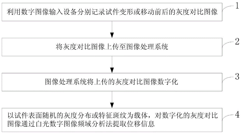
[0041] Such as figure 1 As shown, a deep foundation pit detection method based on white light digital image frequency domain analysis method provided by the present invention includes the following steps:

[0042] Step S1: Using a digital image input device to record the gray contrast images of the specimen before and after deformation or movement.

[0043] Digital image input devices include CCD cameras, digital cameras, photoelectric scanners, and digital video cameras.

[0044] Step S2: Upload the grayscale contrast image to the image processing system;

[0045] Step S3: the image processing system digitizes the uploaded grayscale c...


PUM


Abstract

The invention provides a deep foundation pit detection method based on a white-light digital image frequency domain analysis method. The deep foundation pit detection method includes the following steps: step 1, utilizing digital image input equipment to respectively record deformation of a test piece or gray level comparison images before and after moving; step 2, uploading the gray level comparison images to an image processing system; step 3, digitalizing the uploaded gray level comparison images by the image processing system; step 4, taking random gray level distribution or feature stripe on the surface of the test piece as a carrier to extract displacement information from the digitalized gray level comparison images through the white-light digital image frequency domain analysis method. A testing system in the white-light digital image frequency domain analysis method is simple, no special treatment is needed for the testing surface generally, testing conditions are simple, a vibration isolating platform is not needed, and the deep foundation pit detection method can be used in any place, thereby being wide in application range.

Description

technical field [0001] The invention belongs to the field of displacement and deformation measurement, and in particular relates to a deep foundation pit detection method based on a white light digital image frequency domain analysis method. Background technique [0002] A deep foundation pit is a temporary pit excavated for the foundation of a building structure. Its function is to provide space for the smooth development of the foundation construction, so that the masonry work of the structure can be carried out according to the position specified by the design. The foundation pit support system is a temporary structure with a small safety reserve and high risk. Monitoring should be carried out during the construction of foundation pit engineering, and emergency measures should be taken. Foundation pit engineering monitoring refers to the use of precision instruments and equipment to monitor the displacement, inclination, settlement, stress, cracking, Comprehensive monit...

Claims


Application Information

Patent Timeline
Patent Type & Authority Applications(China)
IPC IPC(8): G01B11/02G01B11/16
Inventor 杨新伟李君君石文广战启芳田瑞兰刘晓庆
Owner SHIJIAZHUANG INST OF RAILWAY TECH
Why Eureka
Try Eureka