Parallel mechanism capable of performing spatial apocenter movement
A space telecentric and telecentric point technology, applied in the field of medical robots, can solve the problems of affecting the quality of abdominal surgical incisions, large and complex series mechanism, poor surgical cutting effect, etc., to reduce motion interference, compact and simple structure, and restore hand and eye. The effect of coordination
- Summary
- Abstract
- Description
- Claims
- Application Information
AI Technical Summary
Problems solved by technology
Method used
Image
Examples
specific Embodiment approach 1
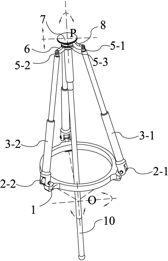
[0033] Specific implementation mode one: combine figure 1 and Figure 5 Describe this embodiment, in this embodiment it comprises base 1, moving platform 7, apparatus 10, one group of UPR motion branch chains and two groups of UPRR motion branch chains, and described base 1 is an annular base, and described moving platform 7 is located directly above the base 1, and the instrument 10 is connected to the moving platform 7 through the annular base. There are three installation shaft holes evenly distributed on the base 1, and the axes of the three installation shaft holes meet at a point on the center line of the base. O, O point is the motion telecentric point;
[0034] A set of UPR motion branch chains includes a central swing link 8, a first rotating pair 5-1, a first telescopic link 3-1 and a first U pair 2-1, and one end of the central swing link 8 is fixedly connected to the moving platform 7, the other end of the central swing rod 8 is connected to the upper end of the ...
specific Embodiment approach 2
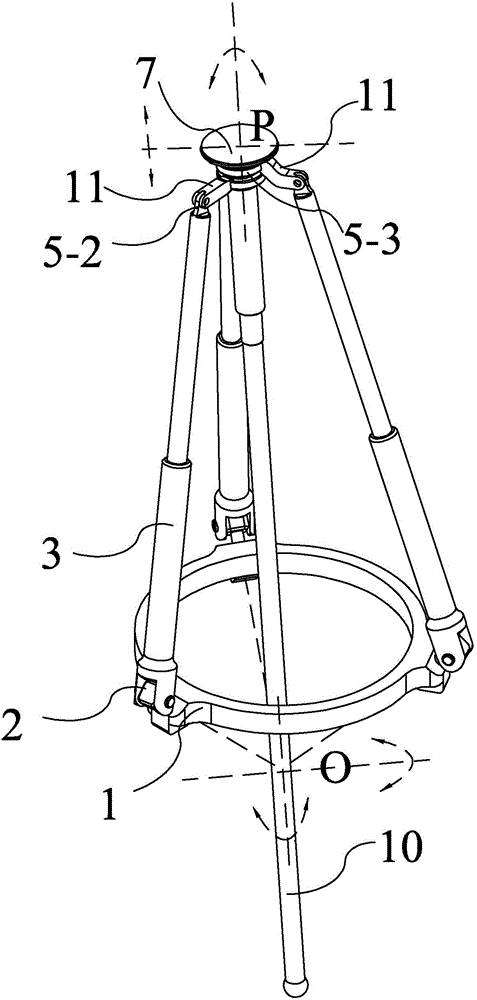
[0039] Specific implementation mode two: combination figure 2 and Figure 6 This embodiment is described. In this embodiment, a parallel mechanism that can realize the movement of the remote point in space is characterized in that it includes a base 1, a moving platform 7, an apparatus 10, and three sets of UPRR motion branch chains. The base 1 is an annular base, the moving platform 7 is located directly above the base 1, the instrument 10 passes through the annular base and is connected to the moving platform 7, three mounting shaft holes are evenly distributed on the base 1, and the three mounting shaft holes The axes meet at a point O on the center line of the base, and the point O is the far center point of the movement;
[0040] Each group of UPRR motion branch chains includes a swing link 11, a third turning pair 5-3, a second turning pair 5-2, a telescopic link 3 and a U pair 2, and one end of the swing link 11 passes through the third turning pair 5 -3 is connected...
specific Embodiment approach 3
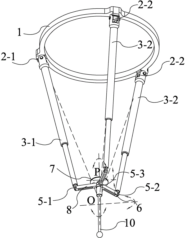
[0043] Specific implementation mode three: combination image 3 and Figure 7 Describe this embodiment, in this embodiment it comprises base 1, moving platform 7, apparatus 10, one group of UPR motion branch chains and two groups of UPRR motion branch chains, and described base 1 is an annular base, and described moving platform 7 is located directly below the base 1. The instrument 10 is connected to the bottom end of the moving platform 7. There are three mounting shaft holes evenly distributed on the base 1. The axes of the three mounting shaft holes meet at a point O on the center line of the base. Point O is the motion telecentric point;
[0044] A set of UPR motion branch chains includes a central swing link 8, a first rotating pair 5-1, a first telescopic link 3-1 and a first U pair 2-1, and one end of the central swing link 8 is fixedly connected to the moving platform 7, the other end of the central swing rod 8 is connected to the lower end of the first telescopic r...
PUM
 Abstract
Description
Claims
Application Information
 - R&D
- Intellectual Property
- Life Sciences
- Materials
- Tech Scout
- Unparalleled Data Quality
- Higher Quality Content
- 60% Fewer Hallucinations
Browse by: Latest US Patents, China's latest patents, Technical Efficacy Thesaurus, Application Domain, Technology Topic, Popular Technical Reports.
© 2025 PatSnap. All rights reserved.Legal|Privacy policy|Modern Slavery Act Transparency Statement|Sitemap|About US| Contact US: help@patsnap.com


