Rectangular secondary battery
A secondary battery, square technology, applied in the field of square secondary batteries, to achieve the effect of maintaining airtightness and high impact resistance
- Summary
- Abstract
- Description
- Claims
- Application Information
AI Technical Summary
Problems solved by technology
Method used
Image

Examples
no. 1 Embodiment approach
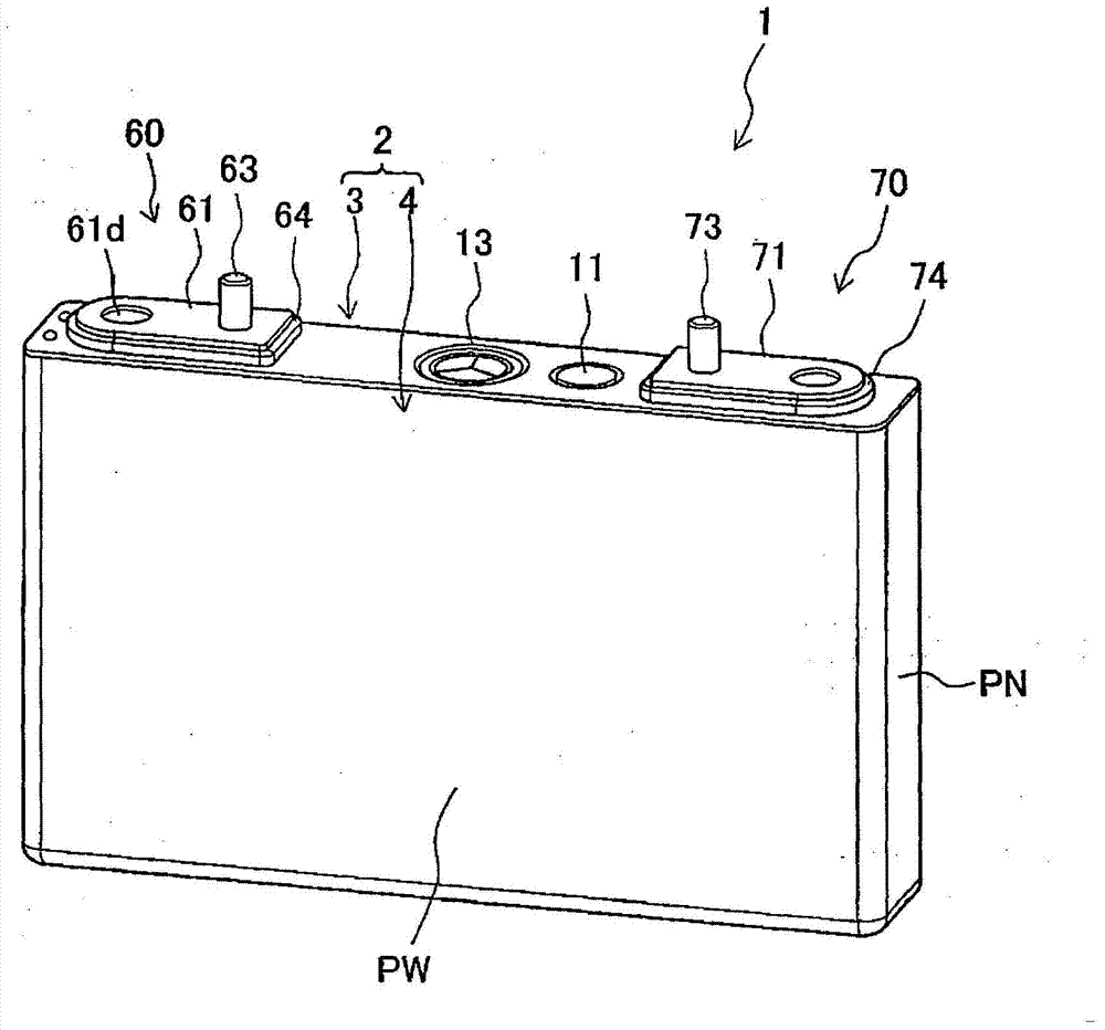
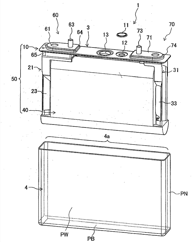
[0024] figure 1 is an external perspective view of the lithium ion secondary battery of the present embodiment, figure 2 yes figure 1 An exploded perspective view of the lithium-ion secondary battery shown.
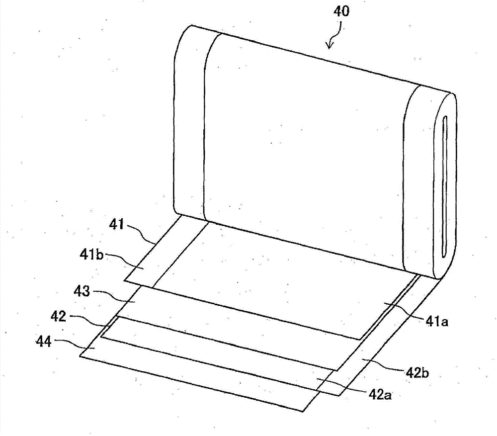
[0025] Such as figure 1 as well as figure 2 As shown, the lithium ion secondary battery 1 has a structure in which a power generating element is housed in a battery container 2 having a square deep-drawn battery can 4 and a battery cover 3 that seals the opening 4 a of the battery can 4 . The power generation element has the electrode group 40 wound in a flat shape with separators 43 and 44 interposed between the positive electrode 41 and the negative electrode 42 . The electrode group 40 is inserted into the battery can 4 together with the positive electrode current collector plate 21 and the negative electrode current collector plate 31 with the outside thereof covered with an insulating sheet (not shown).
[0026] Both the battery can 4 and the battery cover 3 a...
no. 2 Embodiment approach
[0100] Next, use Figure 7 A second embodiment of the present invention will be described.
[0101] Figure 7 It is an enlarged cross-sectional view showing a main part of a quadrangular secondary battery according to the second embodiment. In addition, the same code|symbol is attached|subjected to the same component as 1st Embodiment, and the detailed description is abbreviate|omitted.
[0102] In the present embodiment, it is characterized in that the second insulator 65 is set to the engagement means of the battery cover 3 to be directly fixed only by caulking of the convex part 3b to the inside of the battery of the battery cover 3, and the second insulator 65 is removed. The shaft portion 61c of the positive terminal 61 is fixed by caulking.
[0103] In the first embodiment, as a method of fixing the second insulator 65 to the battery cover 3, a combination of directly fixing the shaft portion 61c of the positive terminal 61 and crimping the convex portion 3b to the in...
no. 3 Embodiment approach
[0109] Next, use Figure 8 A third embodiment of the present invention will be described.
[0110] Figure 8 It is an enlarged cross-sectional view showing a main part of a quadrangular secondary battery according to the third embodiment. In addition, the same code|symbol is attached|subjected to the same component as each above-mentioned embodiment, and the detailed description is abbreviate|omitted.
[0111] In the present embodiment, a case will be described in which the positive electrode side terminal structure portion 60 has a structure without the current interruption means.
[0112] The positive terminal 61 is composed of a flat plate portion 61 a and a shaft portion 69 (electrode terminal portion) as separate bodies. A bus bar (not shown) is connected to the upper surface of the flat plate portion (external terminal) 61 a , and a bus bar connection terminal (not shown) is fixed to a terminal bolt 63 . The flat plate portion 61 a forms an opening portion 61 d commu...
PUM
 Abstract
Description
Claims
Application Information
 - R&D
- Intellectual Property
- Life Sciences
- Materials
- Tech Scout
- Unparalleled Data Quality
- Higher Quality Content
- 60% Fewer Hallucinations
Browse by: Latest US Patents, China's latest patents, Technical Efficacy Thesaurus, Application Domain, Technology Topic, Popular Technical Reports.
© 2025 PatSnap. All rights reserved.Legal|Privacy policy|Modern Slavery Act Transparency Statement|Sitemap|About US| Contact US: help@patsnap.com