
Remote control door lock system and realization method

A remote control and door lock technology, applied in smart home, security, hotel fields, can solve the problems of unreliable network, difficult commercialization, high power consumption, etc.

Inactive Publication Date: 2015-07-15
李凯
View PDF5 Cites 19 Cited by
  • Summary
  • Abstract
  • Description
  • Claims
  • Application Information

AI Technical Summary

Problems solved by technology

[0004] Zigbee protocol, the door lock comes with a zigbee module, prepare a zigbee host at home, and the zigbee host is connected to the router at home. This solution can realize the function of remotely controlling the door lock. The advantage is low power consumption, and it can also use 4 AA batteries The cost of power supply for more than 1 year is relatively acceptable, but because of the unreliability of the network, once there is a power outage or network disconnection, the router cannot be used, and the door cannot be opened
[0005] GPRS protocol, the SIM card can be inserted into the door lock, and the SIM can be connected to the Internet at any time. The advantage of this solution is that it has relatively good reliability because it does not need to rely on the network, but the power consumption is very high, and ordinary batteries cannot be used for more than 1 week. Because commercialization is very difficult
[0006] wifi protocol, the door lock comes with a wifi module, directly connected to the router at home, the reliability is relatively good, but at the same time consumes a lot of power, and it cannot be used when the power is off
[0007] At the same time, there are also some low-power door locks on the market that cannot be remotely controlled, such as Bluetooth door locks, which can be unlocked using the Bluetooth function of the mobile phone, so they do not depend on the network, so they have low power consumption and are easy to use. 4 AA batteries can be used for more than 1 year; strong versatility; simple installation and other advantages, but because it is not connected to the Internet, remote control cannot be realized, and the current status cannot be obtained remotely

Method used


Image

  • Remote control door lock system and realization method
  • Remote control door lock system and realization method
  • Remote control door lock system and realization method

Examples


Embodiment Construction

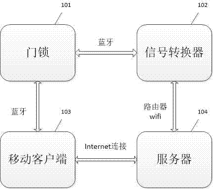
[0028] figure 1 It is a schematic composition diagram of the present invention. The present invention is made up of following several aspects altogether:

[0029] Door lock 101: The interior includes the lock body, lock body, and front and rear handles to realize the mechanical structure of the door lock, and also includes a PCB circuit board. The circuit board includes at least one or more processors, memories, one or more A plurality of modules, the one or more modules are configured and operated by the processor, used to realize: Bluetooth communication, data processing, control the rotation of the motor according to data feedback, obtain the current door lock status, and broadcast the status of the door lock through Bluetooth , bluetooth connection and send out.

[0030] The mechanical structure of the door lock 101 is based on the existing general door lock design on the market, but the difference is that it has a Bluetooth module. The difference between the Bluetooth ...


PUM


Abstract

The invention provides a remote control door lock system. The remote control door lock system comprises: a door lock, which is internally provided with a mechanical structure including a lock body, a lock pin and front and back handles and used for realizing locking of the door lock, and further provided with a PCB circuit board; a signal converter, which is used for mutual conversion of WiFi and Bluetooth and powered by a household electrical circuit; a server, which is arranged in a computer room, based on current Internet technology and used for realizing network communication with the signal converter and mobile equipment and processing and storing a variety of data; and a mobile equipment client, which is based on current Internet technology, operated on a variety of great operation platforms and used for realizing network communication with the server, Bluetooth and / or WiFi communication with the signal converter and Bluetooth communication with the door lock and for processing and storing a variety of data.

Description

technical field [0001] A remote-controlled door lock system and implementation method are used in smart homes, hotels, security and other fields, especially in smart homes, hotels, and security fields that require remote control. Background technique [0002] Smart home is the direction of the future. At present, many of them are making home-only products. Door locks are the first and most important product of smart home, because anyone needs to enter the door to use other smart homes. [0003] At present, many companies are developing door locks that can be remotely controlled. The main solutions include: [0004] Zigbee protocol, the door lock comes with a zigbee module, prepare a zigbee host at home, and the zigbee host is connected to the router at home. This solution can realize the function of remotely controlling the door lock. The advantage is low power consumption, and it can also use 4 AA batteries The cost of power supply for more than one year is relatively acc...

Claims


Application Information

Patent Timeline
IPC IPC(8): G07C9/00
Inventor 不公告发明人
Owner 李凯
Learn More