
Reaeration device and reaeration method for constructed wetland

A technology of artificial wetlands and wetlands, applied in the direction of biological treatment devices, chemical instruments and methods, and restoration of contaminated soil, etc., can solve the problem that the reoxygenation amount per unit of subsurface wetland matrix cannot meet actual needs, affect the purification effect of subsurface flow wetlands, and hydraulic retention Long time and other problems, to achieve the effect of simple structure, low maintenance cost and low cost

Inactive Publication Date: 2015-07-15
RES INST OF FORESTRY NEW TECH CHINESE ACAD OF FORESTRY
View PDF1 Cites 2 Cited by
  • Summary
  • Abstract
  • Description
  • Claims
  • Application Information

AI Technical Summary

Problems solved by technology

However, during the operation of subsurface flow wetlands, due to the long hydraulic retention time and unstable water pressure difference of the existing technical methods, the unit reoxygenation amount of the subsurface flow wetland matrix is ​​difficult to meet the actual demand, which affects the purification effect of subsurface flow wetlands.
At the same time, in the prior art, there is also a method of using a motor blower device to blow air and blow oxygen to the PVC pipe inserted in the matrix. Although to a certain extent, it can better meet the actual needs than the above method, and the reoxygenation effect is also better. , but the general unit cost is high and the process is complicated
There are no reports of such techniques

Method used


Image

  • Reaeration device and reaeration method for constructed wetland
  • Reaeration device and reaeration method for constructed wetland
  • Reaeration device and reaeration method for constructed wetland

Examples


Embodiment 1、1

[0033] Embodiment 1, No. 1 reoxygenation device

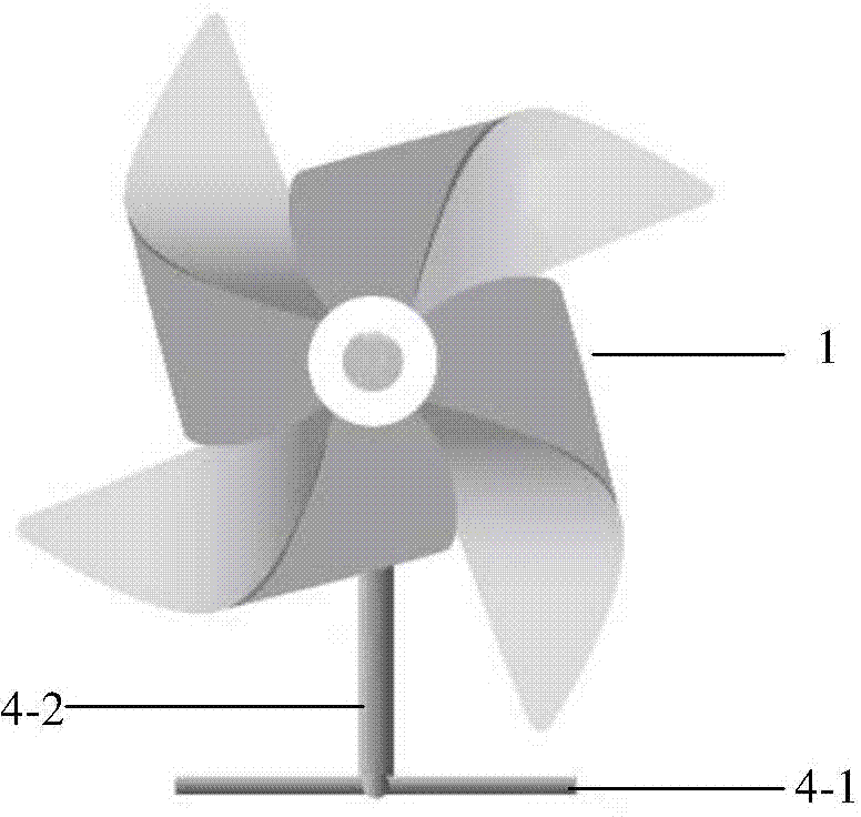
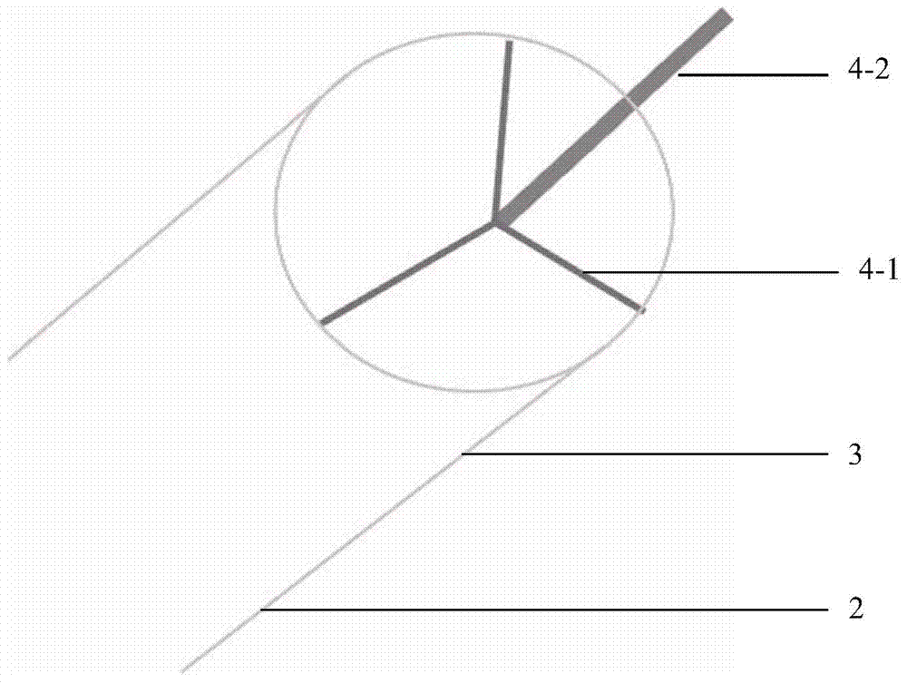
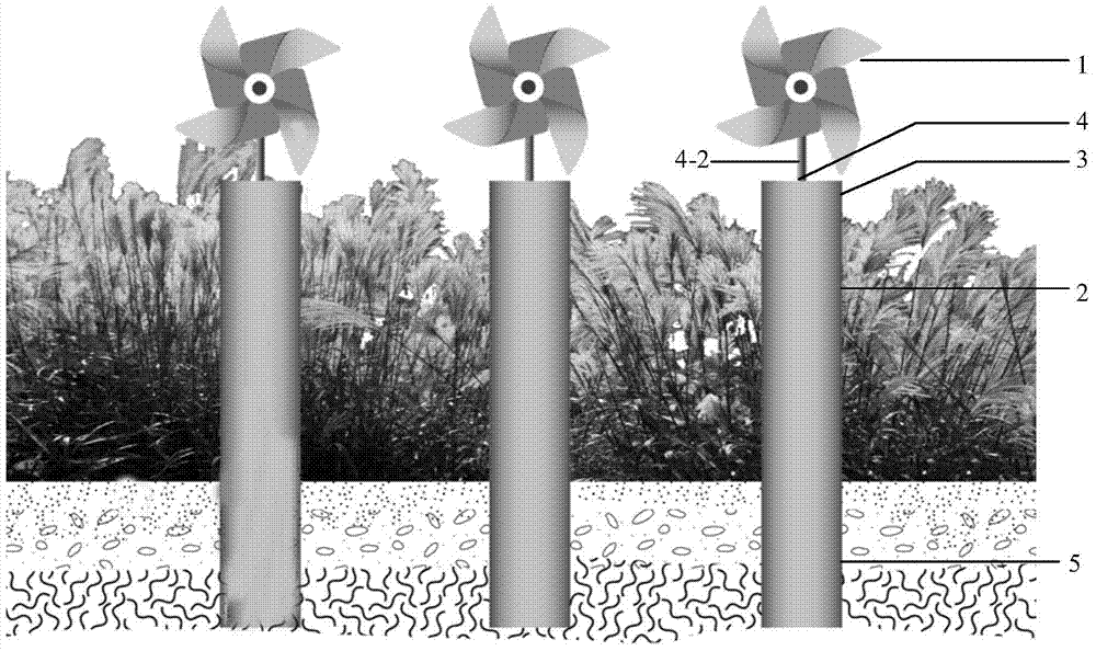
[0034] combine figure 1 , figure 2 and image 3 The No. 1 reoxygenation device for constructed wetlands based on this embodiment will be described in detail. The reoxygenation device comprises a windmill 1 and a reoxygenation pipe 2; the structural representation of the windmill 1 is as follows figure 1 Shown; specifically, in this embodiment, the number of the windmill 1 is one. The reoxygenation tube 1 is a tubular structure with openings at both ends, wherein the end inserted and fixed in the matrix of the constructed wetland is the insertion end 5, which is used to discharge the air in the reoxygenation tube into the matrix; The other end is a free end 3 for receiving air. Such as figure 2 As shown, the free end 3 and the windmill are provided with connecting parts that cooperate with each other for installing the windmill 1 on the free end 3 of the reoxygenation tube 2, and the mutual cooperation of the connecting ...

Embodiment 2、2

[0036] Embodiment 2, No. 2 reoxygenation device

[0037] combine figure 1 , Figure 4 and Figure 5 The No. 2 reoxygenation device based on this embodiment is further described. The No. 2 reoxygenation device includes a windmill 1 and a reoxygenation tube 2; the structural representation of the windmill 1 is as follows figure 1 Shown; Specifically, in this embodiment, the No. 2 reoxygenation device is provided with a windmill 1. The reoxygenation tube 2 includes a plurality of inner tubes 6 with openings at both ends, different inner diameters, and different lengths. The gap, from the outermost inner tube to the innermost inner tube, the inner tube insertion end 6-2 increases sequentially, the specific structure is as follows Figure 4 As shown; the reoxygenation device is prepared by an integrated molding process. This structure is convenient to insert into the wetland matrix, and the material is environmentally friendly and low in cost. Since the inner pipes 6 have dif...

Embodiment 3、3

[0039] Embodiment 3, No. 3 reoxygenation device

[0040] combine figure 1 , Figure 6 and Figure 7 The No. 3 reoxygenation device based on this embodiment is further described. The No. 3 reoxygenation device includes a windmill 1 and a reoxygenation tube 2; the structural representation of the windmill 1 is as follows figure 1 Specifically, in this embodiment, the No. 2 reoxygenation device is provided with two windmills 1 . The reoxygenation tube 2 includes a plurality of inner tubes 6 with openings at both ends and different lengths. The inner tubes are arranged in parallel, and there are gaps for air to flow between adjacent inner tubes. The specific structure is as follows: Figure 6 As shown; the reoxygenation device is prepared by an integrated molding process. This structure is convenient to insert into the wetland matrix, and the material is environmentally friendly and low in cost. Since the inner pipes 6 have different lengths, their insertion ends 6-2 can be i...


PUM


Abstract

The invention relates to a reaeration device and reaeration method for constructed wetland. A reaeration pipe is an open-ended tubular structure, one end of the pipe is inserted into a wetland substrate, and the other end is connected to a windmill to receive and accelerate the air flow. The reaeration pipe can also be formed by coaxial telescoping or parallel arrangement of several open-ended reaeration pipes with different pipe diameters and lengths, and the reaeration pipe is connected to the windmill to jointly form the reaeration device. The invention also provides the method for constructed wetland reaeration with the reaeration device. The reaeration device provided by the invention has the characteristics of simple structure, environment-friendly materials, and low cost. The method using the device to perform constructed wetland reaeration has the advantages of simplicity and practicability, energy saving and environmental protection, low maintenance cost, good reaeration effect, high operation efficiency, and wide application scope.

Description

technical field [0001] The invention belongs to the technical field of ecological engineering, and relates to a reoxygenation device and a reoxygenation method for artificial wetlands. Background technique [0002] As a type of constructed wetland, subsurface wetlands have a relatively small footprint and play a synergistic role in substrate physical, chemical and biological purification, and have good effects in treating pollutants such as organic matter and nitrogen and phosphorus nutrients in sewage. The sewage treatment capacity has been greatly improved, and it has been widely used in practice. [0003] The oxygen content in the substrate of subsurface wetlands is low, and the interior of the wetlands is in a state of anoxic conditions, which easily leads to a decrease in the removal rates of total nitrogen, COD and BOD. In order to solve this problem, in the process of constructing subsurface flow wetlands, the common practice is to insert PVC pipes into the substrate...

Claims


Application Information

Patent Timeline
Patent Type & Authority Applications(China)
IPC IPC(8): C02F3/32B01F23/30
CPCC02F3/02C02F3/32C02F2203/006C02F3/04C02F3/205C02F3/308C02F3/327Y02W10/33Y02A40/22Y02W10/10B09C1/00A01B1/243B09C2101/00B01F23/39B01F23/34A01B45/02
Inventor 崔丽娟赵欣胜李伟张曼胤
Owner RES INST OF FORESTRY NEW TECH CHINESE ACAD OF FORESTRY
Learn More