Core rod groove grinding equipment

A mandrel and grinding technology, used in grinding/polishing equipment, grinding feed motion, grinding workpiece support, etc., can solve the problems of poor grinding accuracy, skin and respiratory tract damage, low work efficiency, etc. High cutting precision, high processing efficiency, and the effect of preventing human injury

Inactive Publication Date: 2015-07-15
南京市宏伟屠宰机械制造有限公司
View PDF7 Cites 0 Cited by
  • Summary
  • Abstract
  • Description
  • Claims
  • Application Information

AI Technical Summary

Problems solved by technology

The main processing method of the mandrel groove is manual grinding, which has low work efficiency and poor grinding accuracy; and because the raw materials of the mandrel are often harmful to the human body such as glass fiber and resin, the extremely fine dust formed during manual grinding , long-term exposure will cause serious damage to human skin, respiratory tract, etc.

Method used


Image

  • Core rod groove grinding equipment
  • Core rod groove grinding equipment
  • Core rod groove grinding equipment

Examples


Embodiment Construction

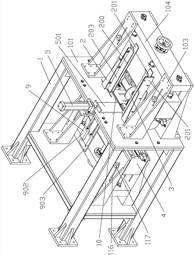
[0049] see figure 1 shown Mandrel groove grinding equipment , including a fuselage 1, a feeding box 2, an upper grinding mechanism 3, a lower grinding mechanism 4, a feeding mechanism 5, an upper pressing mechanism 6, a side pressing mechanism 7, a clamping mechanism 8, and a gravity turning device 9.

[0050] Fuselage 1 is the basis of the whole equipment, including workbench, bed legs, upper column, lower column, upper beam, lower beam and so on. Four bed legs 102 support the workbench 101, and the top of the workbench is fixed with four upper columns 103, and the upper beam 104 is fixedly connected with the upper ends of the four upper columns. There is a platen 105 fixed on the four bed legs below the workbench, four lower columns 106 are fixed on the platen 105, and the lower crossbeam 107 is fixedly connected with the lower ends of the four upper columns.

[0051] The feed box comprises two vertical channels 200 in which the two ends of the mandrel 10 are located. ...


PUM


Abstract

The invention provides core rod groove grinding equipment which is capable of automatically grinding a groove in a core rod and is higher in grinding accuracy and processing efficiency. The core rod groove grinding equipment comprises a machine body, a feeding box, a feeding mechanism, an upper grinding mechanism, a lower grinding mechanism and a lateral pressing mechanism, wherein a discharging opening capable of allowing the entering and exiting of the core rod is formed between the feeding box and a workbench; a pushing plate of the feeding mechanism pushes the core rod into the lower part of an upper abrasive wheel and the upper part of a lower abrasive wheel; the lateral pressing mechanism comprises a floating lateral pressing plate and a lateral pressing backing plate connected to the workbench; a lateral pressing spring is arranged between the floating lateral pressing plate and the workbench; when the lateral pressing spring is in a normal state, the floating lateral pressing plate presses the core rod, which is horizontally pushed down by the pushing plate and horizontally moves on the workbench, between the floating lateral pressing plate and the lateral pressing backing plate; the lateral pressing backing plate is arranged on the workbench in a direction parallel to the axis of the core rod in a left-right movable way according to the structure that a sliding groove parallel to the axis of the core rod is formed in the lateral pressing backing plate and a butterfly bolt passes through the sliding groove and the workbench and is matched with a nut.

Description

technical field [0001] The technology relates to a mandrel groove grinding equipment for grinding grooves on a mandrel with oblate, flat or rectangular cross section. Background technique [0002] A hammer is a commonly used hitting tool, which can cause displacement or deformation by hitting an object. A hammer is usually composed of a hammer head and a hammer handle. The hammer handle is the main grasping part of the user, and its shape, size, material, structure, etc. directly affect the actual use effect of the hammer. The hammer handle is generally composed of an oblate mandrel and a soft sheath fitted on the mandrel. As the core part of the hammer handle, the mandrel is usually formed by heating and fusing glass fibers, resins, etc., adding other chemical materials, injection molding, cooling, shaping, stretching, and cutting, and then processing several grooves on its surface. The soft sheath is fitted on the groove of the mandrel to prevent the soft sheath from sli...

Claims


Application Information

Patent Timeline
Patent Type & Authority Applications(China)
IPC IPC(8): B24B19/02B24B27/00B24B41/00B24B41/06
CPCB24B19/02B24B27/0076B24B41/005B24B41/06
Inventor 毛凯旸
Owner 南京市宏伟屠宰机械制造有限公司
Why Eureka
Try Eureka