Impeller main shaft sealing device for ocean current energy power generation system

A power generation system and spindle sealing technology, which is applied in hydropower, engine components, machines/engines, etc., can solve the problems of high machining accuracy and installation requirements of sealing components, damage to gearboxes and generator components, and accelerated sealing of sealing components. Achieve the effect of improving energy transfer efficiency, effective sealing and long life

Active Publication Date: 2015-07-08
ZHEJIANG UNIV
View PDF9 Cites 3 Cited by
  • Summary
  • Abstract
  • Description
  • Claims
  • Application Information

AI Technical Summary

Problems solved by technology

As far as the combined oil seal method is concerned, the harsh underwater working conditions will accelerate the wear of the sealing components and cause the seal to fail, resulting in leakage, resulting in damage to the gear box, generator and other components in the engine room, and at the same time causing water pollution.
As far as the floating ring mechanical seal method is concerned, although its sealing effect is good, the leakage is small, and its service life is long, it requires high processing accuracy and installation of sealing components.

Method used


Image

  • Impeller main shaft sealing device for ocean current energy power generation system
  • Impeller main shaft sealing device for ocean current energy power generation system
  • Impeller main shaft sealing device for ocean current energy power generation system

Examples


Embodiment Construction

[0024] The following will clearly and completely describe the technical solutions in the embodiments of the present invention with reference to the accompanying drawings in the embodiments of the present invention. Obviously, the described embodiments are some of the embodiments of the present invention, but not all of them. Based on the embodiments of the present invention, all other embodiments obtained by persons of ordinary skill in the art without making creative efforts belong to the protection scope of the present invention.

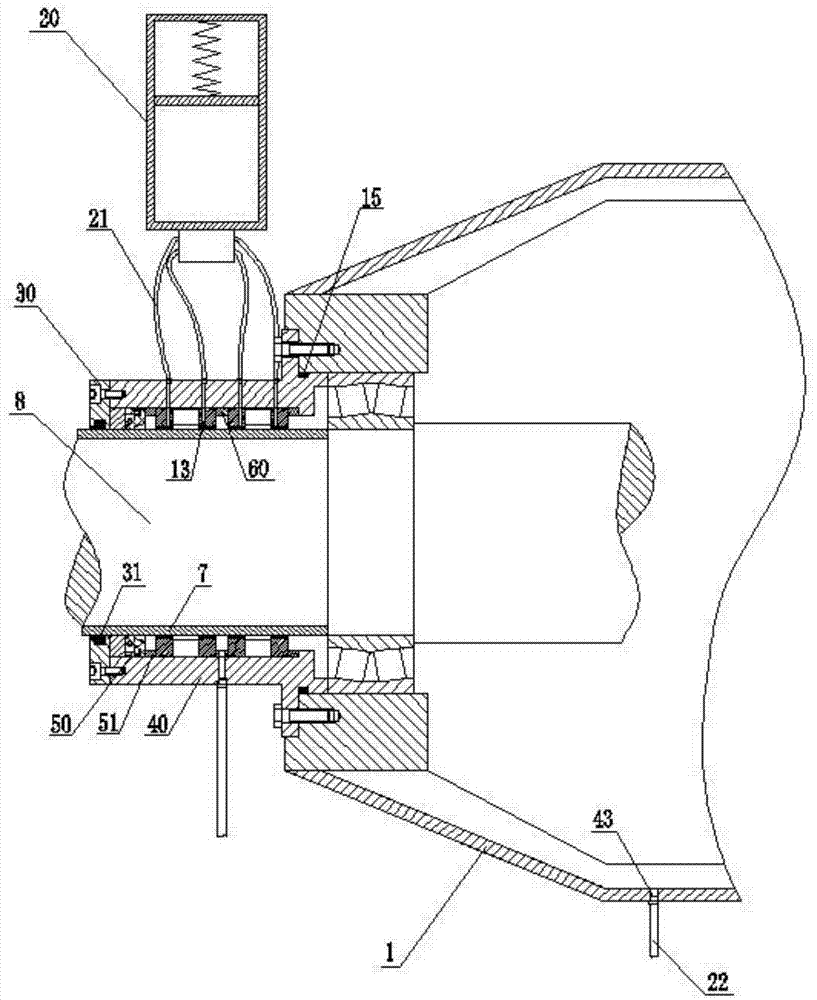
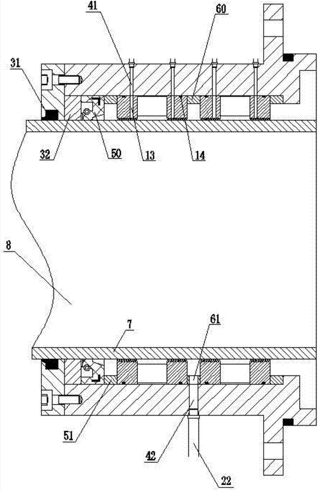
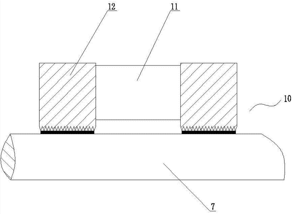
[0025] Refer to attached figure 1 To attach image 3 . A sealing device for the main shaft of the impeller of the ocean current power generation system, the sealing device of the main shaft of the impeller of the ocean current power generation system is fixedly assembled on the nacelle shell 1 of the ocean current power generation system, and is located where the impeller main shaft 8 protrudes from the nacelle shell 1 .

[0026] The sealing dev...


PUM


Abstract

The invention relates to an impeller main shaft sealing device for an ocean current energy power generation system. The sealing device comprises two magnetic fluid sealing pairs, magnetic fluid automatic compensating equipment, a shaft cover, a sealing housing, an inner packing framework oil seal, a wear-resisting sleeve and gas-filling equipment, wherein the shaft cover and the sealing housing are fixed together through a bolt. The sealing housing is of a sleeve type structure; the inner packing framework oil seal, and the two magnetic fluid sealing pairs are of circular-ring type structures; the inner packing framework oil seal and the two magnetic fluid sealing pairs are arranged on the inner surface of the sealing housing in sequence; four first liquid filing holes and a first gas filling hole are formed in the sealing housing; a second gas filling hole is formed in a cabin housing. The magnetic fluid automatic compensating equipment is communicated with the first liquid filling hole; the gas filling equipment is communicated with the first gas filling holes and the second gas filling hole. The sealing device adopts a magnetic fluid sealing technology to realize two-way sealing of the impeller main shaft, and adopts a mode of filling gas with certain pressure to gradually balance the external seawater pressure, so that the magnetic fluid sealing reliability is guaranteed.

Description

technical field [0001] The invention belongs to the field of new energy power generation, and in particular relates to a sealing device for a main shaft of an impeller of an ocean current power generation system. Background technique [0002] The excessive use of fossil energy has made the problems of resource shortage and environmental degradation increasingly prominent. As a clean and renewable ocean energy resource, ocean current energy has the characteristics of abundant reserves, strong regularity, and high energy density. It has become a strategic choice for countries to develop renewable energy. Ocean current power generation system is a new type of mechanical system that utilizes ocean current energy to generate electricity. [0003] For ocean current power generation systems, the seal where the impeller main shaft extends out of the nacelle is one of the key technologies. Due to the harsh working environment of the ocean current power generation system, the impell...

Claims


Application Information

Patent Timeline
Patent Type & Authority Applications(China)
IPC IPC(8): F03B11/00
CPCF03B11/006Y02E10/20
Inventor 顾海港林勇刚丁渊李伟刘宏伟
Owner ZHEJIANG UNIV
Why Eureka
Try Eureka