Non-linear combined spring vibration isolator
A combined vibration isolator technology, applied in the directions of roads, tracks, buildings, etc., can solve the problems of difficulty in raising and leveling the floating ballast bed, limitation of the overall vibration isolation effect, and high natural frequency of the system, so as to improve the overall vibration isolation effect, Good overall vibration reduction and noise reduction effect, low natural frequency effect
- Summary
- Abstract
- Description
- Claims
- Application Information
AI Technical Summary
Problems solved by technology
Method used
Image
Examples
Embodiment 1
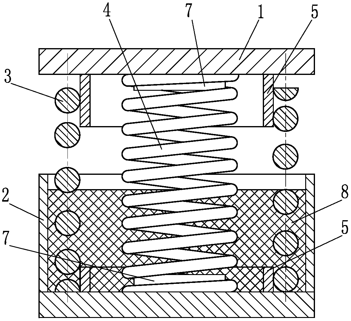
[0021] Such as figure 1 The nonlinear combined elastic vibration isolator shown in the present invention includes an upper shell 1, a lower shell 2 and an elastic element, the elastic element is placed between the lower shell 1 and the lower shell 2, and the elastic element includes a static load Support spring 4 and joint support spring 3, wherein, static load support spring 4 and joint support spring 3 are helical steel springs, the stiffness of static load support spring 4 is less than the stiffness of joint support spring 3, and joint support spring 3 is set in static The load support spring 4 is outside, and the top surface of the static load support spring 4 is higher than the top surface of the joint support spring 3, the static load support spring 4 supports the upper casing 1; the lower casing 2 is provided with a damping material 8, and the static load The support spring 4 and the combined support spring 3 are partially placed in the damping material 8, and the dampi...
Embodiment 2
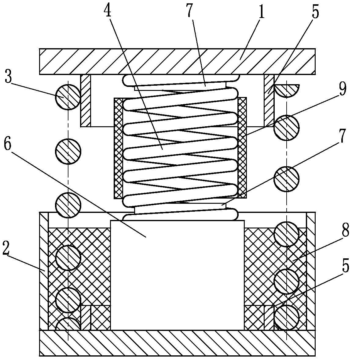
[0027] Such as figure 2 The difference between the nonlinear combined elastic vibration isolator of the present invention and the first embodiment is that the partial surface of the static load support spring 4 is provided with a solid damping structure, and the solid damping structure is specifically sleeved on the static load support spring 4 A rubber sleeve 9 on the local outer surface; in addition, a support 6 for height compensation is provided under the static load support spring 4, and the support 6 is firmly connected with the lower housing 2 as a whole. At this time, the static load support spring 4 The centering and locating member includes the inner centering and locating ring 7 correspondingly provided on the upper shell 1 and the support 6 .
[0028]Compared with Embodiment 1, in the technical solution described in this example, a rubber sleeve 9 is added to the partial outer surface of the static load support spring 4, which can effectively improve the system da...
Embodiment 3
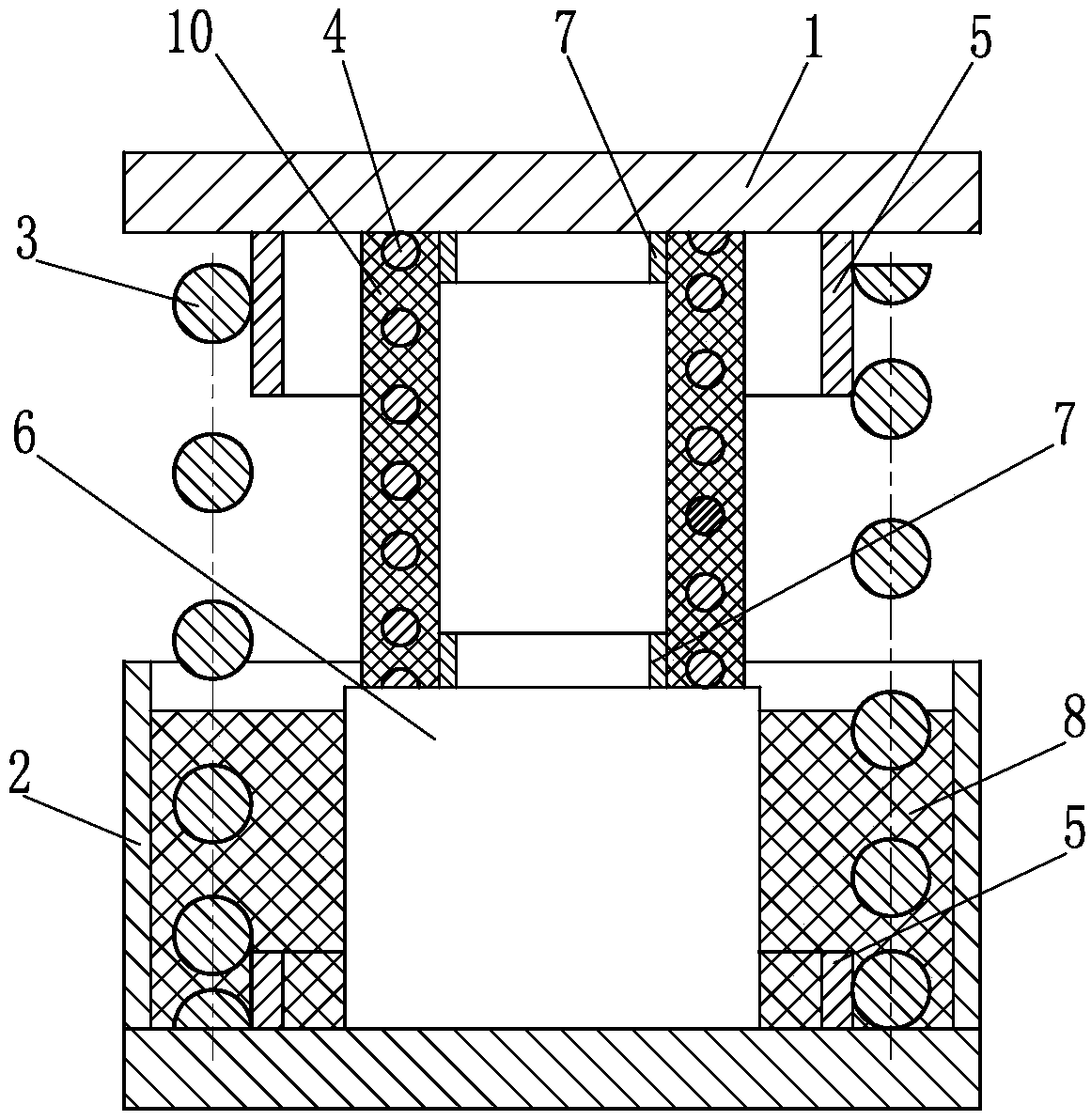
[0030] Such as Figure 4 The nonlinear combined elastic vibration isolator of the present invention shown, and image 3 The difference of the technical solution shown is that the lower housing 2 is only composed of a bottom plate, and the joint support spring 3 and the static load support spring 4 are placed on the lower housing 2; in addition, the partial surface of the joint support spring 3 is provided with a solid damping structure, specifically Yes, the solid damping structure is an elastic polyurethane layer 11 integrated with the partial surface of the support spring 3 .
[0031] Compared with the second embodiment, the technical solution described in this example involves fewer components, a simpler structure, and more convenient maintenance and replacement. Of course, similar to the description of the solid damping structure provided on the surface of the static load support spring 4 in Embodiment 2, the manner in which the solid damping structure is provided on the ...
PUM
 Abstract
Description
Claims
Application Information
 - R&D
- Intellectual Property
- Life Sciences
- Materials
- Tech Scout
- Unparalleled Data Quality
- Higher Quality Content
- 60% Fewer Hallucinations
Browse by: Latest US Patents, China's latest patents, Technical Efficacy Thesaurus, Application Domain, Technology Topic, Popular Technical Reports.
© 2025 PatSnap. All rights reserved.Legal|Privacy policy|Modern Slavery Act Transparency Statement|Sitemap|About US| Contact US: help@patsnap.com


