Jet engine cleaning method and cleaning apparatus

A jet engine and cleaning device technology, applied in the direction of engine components, machines/engines, mechanical equipment, etc., can solve problems such as inability to achieve the effect, achieve the effect of shortening the cleaning time, reducing the processing cost, and improving the cleaning effect

Inactive Publication Date: 2015-07-08
洪圣涛 +1
View PDF6 Cites 8 Cited by
  • Summary
  • Abstract
  • Description
  • Claims
  • Application Information

AI Technical Summary

Problems solved by technology

However, satisfactory results cannot be achieved if the EGT tolerance (tolerance relative to the limitation of the exhaust gas temperature) is included

Method used


Image

  • Jet engine cleaning method and cleaning apparatus
  • Jet engine cleaning method and cleaning apparatus
  • Jet engine cleaning method and cleaning apparatus

Examples


Embodiment Construction

[0048] Embodiments of the present invention will be described below with reference to the drawings.

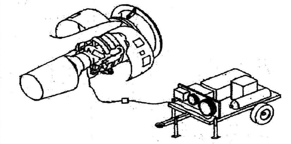
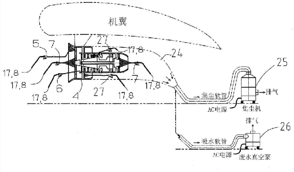
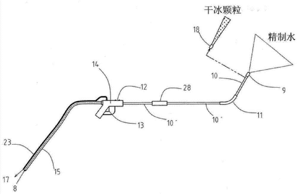
[0049] figure 2It is a figure showing one embodiment of the present invention, and shows a spray head device 5 for cleaning the inner wall surface of the front blade, a stationary wing, and a moving wing with dry ice particles, a spray head device 6 for cleaning the front blade, and a spray head device 7 for cleaning the inside of the engine , and with the spray head arrangement 27 having the flexible tube 16 for cleaning the jet engine 4 example. In the above embodiment, the nozzle device 27 is inserted from the optical fiber inspection port, and sprays dry ice particles, purified warm water (70° C. to 80° C.) and purified water for rinsing for cleaning. in addition, figure 2 Symbol 8 represents a device in which dry ice particles, purified warm water or purified water for rinsing are injected into the injector 14, and the sand or dust peeled off after cleaning with dry i...


PUM


Abstract

The invention discloses a jet engine cleaning method and a cleaning apparatus. High efficient cleaning cna be achieved in short time without the use of chemical cleaning agent and emissions of EGT, SFC and carbon dioxide can be reduced. The cleaning method comprises the following steps of injecting dry ice particles toward the jet engine as the to-be-cleaned object and installed on two sides of a wing. Shake and impact are caused to the surface of dirts due to a burst reaction when plenty of dry ice particles are sent into the engine with high speed engine blade rotation, so dirts break and the dry ice particles can enter the cracks; the dry ice particles can turn into air with expanded size due to the sublimation action of the dry ice; by the use of the above methods, dirts can be peeled off and blown off; and then refined warm water is sprayed, so all remained dirts can be removed.

Description

[0001] This application claims the priority of the Japanese application with the filing date of January 7, 2014 and the application number of JP2014-000913, and incorporates the content of the above application. technical field [0002] The present invention relates to a kind of cleaning method about the jet engine that is installed on the two wings of aircraft, specifically can effectively remove fouling on the aircraft engine, significantly improves EGT tolerance (tolerance with respect to the limit of exhaust gas temperature) Limit) and SFC (Special Fuel Consumption), and significantly reduce the emission (generation) of carbon dioxide jet engine cleaning method and cleaning device. Background technique [0003] When flying for a long time, carbon formed by sand and smoke will be attached to the jet engine of the aircraft, which will increase the fuel consumption of the engine. For this reason, aircraft engines have been cleaned for a long time in order to save fuel. fig...

Claims


Application Information

Patent Timeline
IPC IPC(8): F02B77/04
Inventor 渡边保夫
Owner 洪圣涛
Why Eureka
Try Eureka