The upper and lower connection structure of the prefabricated shear wall

A technology for connecting structures and shear walls, which is applied in the direction of walls, building components, and building structures, and can solve problems such as stress concentration at horizontal joints, difficulty in ensuring the quality of reserved holes, and difficulty in welding quality , to achieve good development prospects, solve construction difficulties, accurate positioning and simple effects

Active Publication Date: 2017-01-25
TIANJIN UNIV RES INST OF ARCHITECTRUAL DESIGN & URBAN PLANNING +1
View PDF6 Cites 0 Cited by
  • Summary
  • Abstract
  • Description
  • Claims
  • Application Information

AI Technical Summary

Problems solved by technology

Sleeve grouting connection has problems such as high sleeve cost, high construction accuracy requirements, and not suitable for steel bars with thinner cross-sections; steel bar welding connection has problems such as heavy on-site welding workload and difficult to guarantee welding quality; indirect lap joint grout Anchor connections have problems such as difficulty in on-site construction and difficulty in ensuring the quality of the reserved holes. Moreover, sleeve grout connections and indirect lap joint grout-anchor connections are dry connections. If not handled properly, stress concentration will easily occur at the horizontal joints Phenomenon, forming a weak section, affecting the overall performance of the structure

Method used


Image

  • The upper and lower connection structure of the prefabricated shear wall
  • The upper and lower connection structure of the prefabricated shear wall
  • The upper and lower connection structure of the prefabricated shear wall

Examples


Embodiment Construction

[0021] In order to further understand the content of the invention, features and effects of the present invention, the following examples are given hereby, and detailed descriptions are as follows in conjunction with the accompanying drawings:

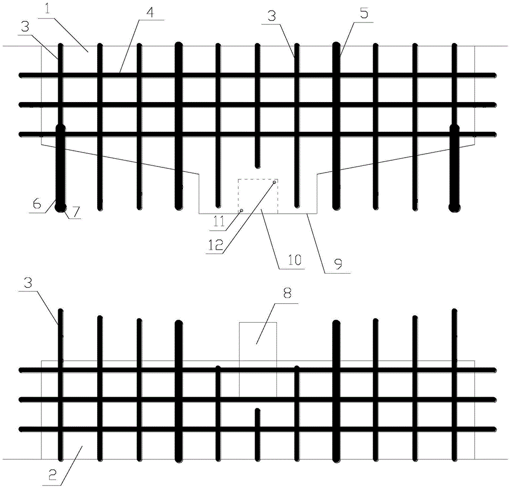
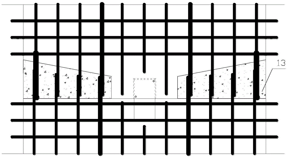
[0022] see Figure 1 to Figure 6 , a lower connection structure of a prefabricated shear wall, the middle part of the bottom surface of the upper wall is provided with a downward protruding platform 9, and a shear groove 10 is provided on the bottom surface of the downward protruding platform 9; the lower wall I-beam 8 is pre-buried in the middle of the top surface of 2; said downward protruding platform 9 is located on the top surface of said lower wall 2, and said I-beam 8 is inserted into said shear groove 10, The I-beam 8 is fixed in the shear groove 10 by the concrete structure poured into the shear groove 10 to form a positioning-shear structure.

[0023] In this embodiment, the bottom surface of the upper wall 1 located on both...


PUM


Abstract

The invention discloses an upper and lower connecting structure of an assembled shearing force wall. The middle part of the bottom face of the upper wall is provided with a downward convex platform; the bottom face of the downward convex platform is provided with an anti-shearing groove; the middle part of the top face of the lower wall is pre-embedded with channel steel or I-steel; the downward convex platform is located on the top face of the lower wall; the channel steel or I-steel is inserted in the anti-shearing groove; the channel steel or I-steel is fixed in the anti-shearing groove by the concrete structure post-casting in the anti-shearing groove, forming a positioning and anti-shearing structure. The positioning and anti-shearing structure, adjusting and supporting structure and post-casting wedge-shaped concrete structure are used, so that the upper and lower connecting construction of the wall is simpler, the positioning is more accurate, the structure is more reliable, and the performance is optimal. The material performance is adequately used, and the problems that the site construction of the current connection mode is difficult and the cost is expensive are effectively solved.

Description

technical field [0001] The invention relates to the field of building structures, in particular to an upper and lower connection structure of a prefabricated shear wall. Background technique [0002] At present, the traditional cast-in-place shear wall structure has problems such as heavy on-site workload, waste of building materials, waste of building water, and serious environmental pollution. The vertical connection structure of the prefabricated shear wall structure mostly adopts sleeve grouting connection, steel bar welding connection and indirect lap joint grouting anchor connection. Sleeve grouting connection has problems such as high cost of sleeve, high construction precision requirements, and unsuitability for steel bars with thinner cross-sections; steel bar welding connection has problems such as heavy on-site welding workload and difficult to guarantee welding quality; indirect lap joint grouting Anchor connections have problems such as difficulty in on-site co...

Claims


Application Information

Patent Timeline
Patent Type & Authority Patents(China)
IPC IPC(8): E04B2/84
Inventor 张锡治田杰松凌光荣马健蔡魏巍
Owner TIANJIN UNIV RES INST OF ARCHITECTRUAL DESIGN & URBAN PLANNING
Why Eureka
Try Eureka