Flue gas desulphurization system

A desulfurization system and flue gas technology, applied in the separation of dispersed particles, chemical instruments and methods, separation methods, etc., can solve the problems of large fluctuation of flue gas volume, large fluctuation of system load, and excessive concentration

Inactive Publication Date: 2015-07-08
JINLONG COPPER
View PDF8 Cites 1 Cited by
  • Summary
  • Abstract
  • Description
  • Claims
  • Application Information

AI Technical Summary

Problems solved by technology

However, in the actual production process, due to the large fluctuations in the amount of flue gas generated in the smelting / converting furnace, and the SO in the flue gas 2 Concentrations are high, these high concentrations of SO 2 Low-concentration SO produced in smelting furnaces such as flue gas and anode furnaces 2 When the flue gas is mixed and enters the desulfurization tower of the desulfurization system for desulfurization, once the amount of flue gas in the smelting / converting furnace increases instantaneously, the SO in the flue gas 2 When the concentration becomes larger, the desulfurization tower will not be able to adapt to the instantaneous high-load flue gas changes, resulting in the system tail SO 2 Concentration exceeding the standard
In order to solve the problem of fluctuating flue gas to be treated, copper mining enterprises need to design the desulfurization tower and its supporting facilities according to the peak value of the flue gas to be processed, resulting in very high investment costs for equipment and raw materials such as desulfurizers
In addition, when treating flue gas with the magnesium oxide method, due to the large fluctuation of the system load, when the load suddenly decreases, due to the lag of the system control, the slurry containing magnesium oxide in the desulfurization agent cannot be completely converted into magnesium sulfite, which will cause the desulfurization agent Loss

Method used


Image

  • Flue gas desulphurization system
  • Flue gas desulphurization system

Examples


Embodiment Construction

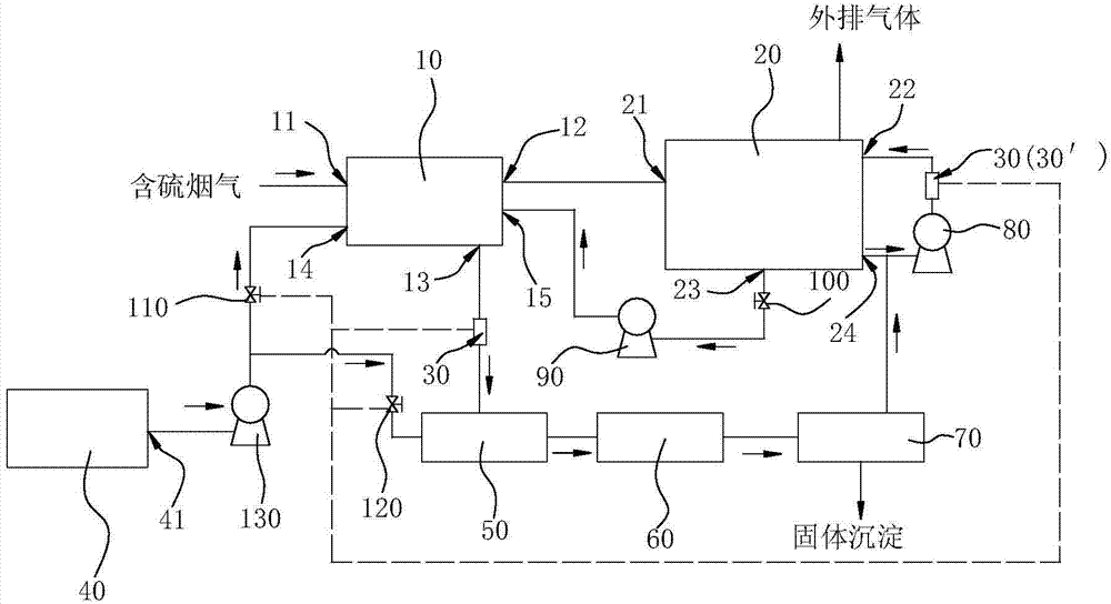
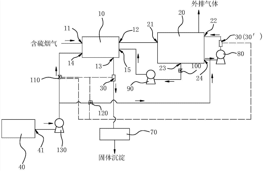
[0007] A flue gas desulfurization system, which includes a pre-desulfurization tower 10 and a main desulfurization tower 20, the smoke inlet 11 of the pre-desulfurization tower 10 is connected with the flue gas outlet of the smelting furnace, and the smoke outlet 12 of the pre-desulfurization tower 10 is connected with the main desulfurization tower 10. The air inlet 21 of the desulfurization tower 20 is connected, and the liquid outlet 13 of the pre-desulfurization tower 10 and / or the desulfurizer inlet 22 of the main desulfurization tower 20 are provided with a metering mechanism 30, and the metering mechanism 30 includes a control unit and a pH value The detection unit, the pH value detection unit detects the pH value of the liquid in the pipeline and sends the pH value signal to the control unit, and the control unit receives the pH value signal and controls and adjusts the desulfurizer input into the pre-desulfurization tower 10 and / or the main desulfurization tower 20 flo...


PUM


Abstract

The invention discloses a flue gas desulphurization system, which comprises a predesulfurization tower and a main desulfurization tower, a flue gas inlet of the predesulfurization tower is connected to a flue gas outlet of a smelting furnace, the flue gas outlet of the predesulfurization tower is connected to the flue gas inlet of the main desulfurization tower, a metering mechanism is arranged at a liquid outlet of the predesulfurization tower and / or a desulfurizer inlet of the main desulfurization tower, the metering mechanism comprises a control unit and a PH value detection unit, the PH value detection unit is used for detecting pH value of the liquid in a pipeline and conveying a PH value signal to the control unit, and the control unit receives the PH value signal and is capable of controlling and adjusting the desulfurizer flow input in the predesulfurization tower and / or the main desulfurization tower. By employing a fractional step method for processing sulfur-containing flue gas, the processed flue gas can effectively reach a discharge standard, furtherly, by detecting the pH value of the liquid, the desulfurizer flow input in the predesulfurization tower and / or the main desulfurization tower can be controlled and adjusted in advance, so that sulfur-containing flue gas can be effectively treated, and desulfurizer utilization rate is increased.

Description

technical field [0001] The invention relates to the field of chemical production, in particular to a flue gas desulfurization system. Background technique [0002] In the process of pyrometallurgical copper smelting, for the sulfur-containing flue gas discharged from the smelting furnace, domestic copper mining enterprises mainly use ionic liquid method, magnesium oxide method, ammonia method, gypsum method, sodium method and other methods to deal with it. Make the flue gas reach SO 2 Emission Standards. However, in the actual production process, due to the large fluctuations in the amount of flue gas generated in the smelting / converting furnace, and the SO in the flue gas 2 Concentrations are high, these high concentrations of SO 2 Low-concentration SO produced in smelting furnaces such as flue gas and anode furnaces 2 When the flue gas is mixed and enters the desulfurization tower of the desulfurization system for desulfurization, once the amount of flue gas in the sme...

Claims


Application Information

Patent Timeline
IPC IPC(8): B01D53/78B01D53/50B01D53/96
Inventor 戴升弘吴新民刘安明王志平汪志全刘会巨周振联
Owner JINLONG COPPER
Why Eureka
Try Eureka