
Medicine dispensing needle

A needle and needle bar technology, applied in the field of medical supplies, can solve the problems of safety of blocked needles, inability to clean the needle tip, hidden dangers, etc., and achieve the effects of increasing the suction volume, reducing the contact area, and reducing waste.

Inactive Publication Date: 2015-07-08
李开雄
View PDF7 Cites 0 Cited by
  • Summary
  • Abstract
  • Description
  • Claims
  • Application Information

AI Technical Summary

Problems solved by technology

But there is a problem in the above-mentioned needle: the edge of the bevel is relatively sharp, and when the needle tip pierces the blocking rubber stopper on the medicine bottle, a small amount of rubber will be cut off by the edge of the bevel, and the cut rubber will block the needle or Entering the human body poses a safety hazard
But there is still a problem with this needle: After the needle is formed, the inside of the needle needs to be flushed to keep the inner wall of the needle clean
However, the above-mentioned needle tip hole is opened on the hollow section, resulting in a part of the hollow section on the needle tip being surrounded by the needle tip wall, and the cleaning liquid enters from the needle handle and flows out directly from the needle tip hole during cleaning, resulting in the cleaning liquid not being able to work well. cleaning the needle tip

Method used


Image

  • Medicine dispensing needle
  • Medicine dispensing needle
  • Medicine dispensing needle

Examples


Embodiment 1

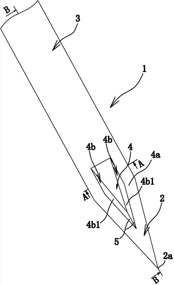
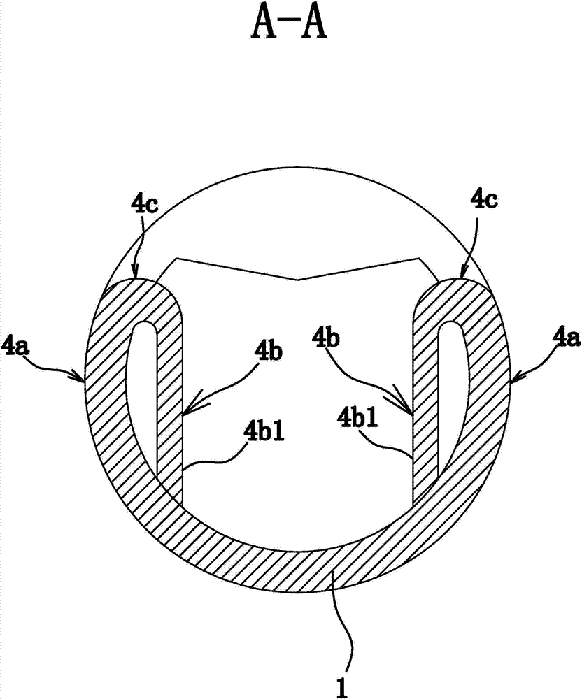
[0032] Such as figure 1 and Figure 4 As shown, the dispensing needle includes a hollow and rod-shaped body 1, the outer surface of the body 1 has a conical needle point 2 and a cylindrical needle shaft 3, and the front end of the needle point 2 is a needle point 2a .

[0033] Such as figure 1 As shown, the junction of the needle shaft part 3 and the needle tip part 2 is provided with a strip-shaped drug inlet hole 4, the drug inlet hole 4 communicates with the inner cavity of the body 1, and the drug inlet hole 4 has a strip-shaped opening. The direction of the shape is consistent with the axial direction of the main body 1. Such as figure 2 As shown, the opening of the medicine inlet hole 4 is the nearest point from the needle tip 2a to the needle tip 2 of the section of the needle tip 2a is a solid cone 2b, that is, the medicine inlet 4 is opened on the solid section of the needle tip 2, so that the needle tip The hollow section on the part 2 is completely exposed to ...

Embodiment 2

[0039] The structure and principle of the second embodiment are basically the same as the first embodiment, the difference is that: Figure 6 As shown, one end of the drug inlet hole 4 located on the needle tip 2 is roughly trapezoidal.


PUM


Abstract

The invention provides a medicine dispensing needle and belongs to the technical field of medical supplies. The medicine dispensing needle solves the problem that an existing medicine dispensing needle is likely to cut off rubber in a rubber plug in a puncture process. The medicine dispensing needle comprises a hollow rod-shaped body, a conical needle point portion and a cylinder needle rod portion are arranged on the outer surface of the body, the joint of the needle rod portion and the needle point portion is provided with a medicine inlet with a strip-shaped aperture, and the strip direction of the aperture of the medicine inlet is identical with the axial direction of the body. The outer surface of the position, at the aperture, of the body is the outer side surface of the medicine inlet, the inner wall, of the position, at the aperture of the body is the inner side surface of the medicine inlet, smooth transition is adopted for the outer side surface and the inner side surface at the aperture, the front end of the needle point portion is a needle point head, and the part, from the point, closest to the needle point head, of the aperture of the medicine inlet to the needle point head, of the needle point portion is a solid cone. The medicine dispensing needle has the three advantages that liquid medicine waste is reduced, clear cleaning is achieved, and rubber of a rubber plug is unlikely to be cut off in a puncture process.

Description

technical field [0001] The invention belongs to the technical field of medical supplies and relates to a medicine dispensing needle. Background technique [0002] Suctioning the liquid medicine in the medicine bottle by the syringe through the needle is a common basic nursing operation, and it is also an auxiliary work for completing the treatment. [0003] The existing needle includes a body, which includes a hollow needle shaft and a needle tip, and an oblique opening is opened on the needle tip. When the needle is in use, it first pierces through the rubber stopper on the medicine bottle through the needle point and enters into the medicine bottle, and then draws the medicinal liquid in the medicine bottle through the oblique opening on the needle point. But there is a problem in the above-mentioned needle: the edge of the bevel is relatively sharp, and when the needle tip pierces the blocking rubber stopper on the medicine bottle, a small amount of rubber will be cut of...

Claims


Application Information

Patent Timeline
IPC IPC(8): A61M5/32A61J1/20
CPCA61M5/3286A61M5/3291
Inventor 李开雄
Owner 李开雄
Learn More