Series feedback balance high-fidelity audio amplifying circuit
An audio amplifier circuit, series feedback technology, applied in negative feedback circuit layout, differential amplifier, DC-coupled DC amplifier, etc., can solve the problems of unstable output and low input impedance, and achieve stable circuit balance and common mode rejection ratio. High and wide frequency response
- Summary
- Abstract
- Description
- Claims
- Application Information
AI Technical Summary
Problems solved by technology
Method used
Image
Examples
Embodiment 1
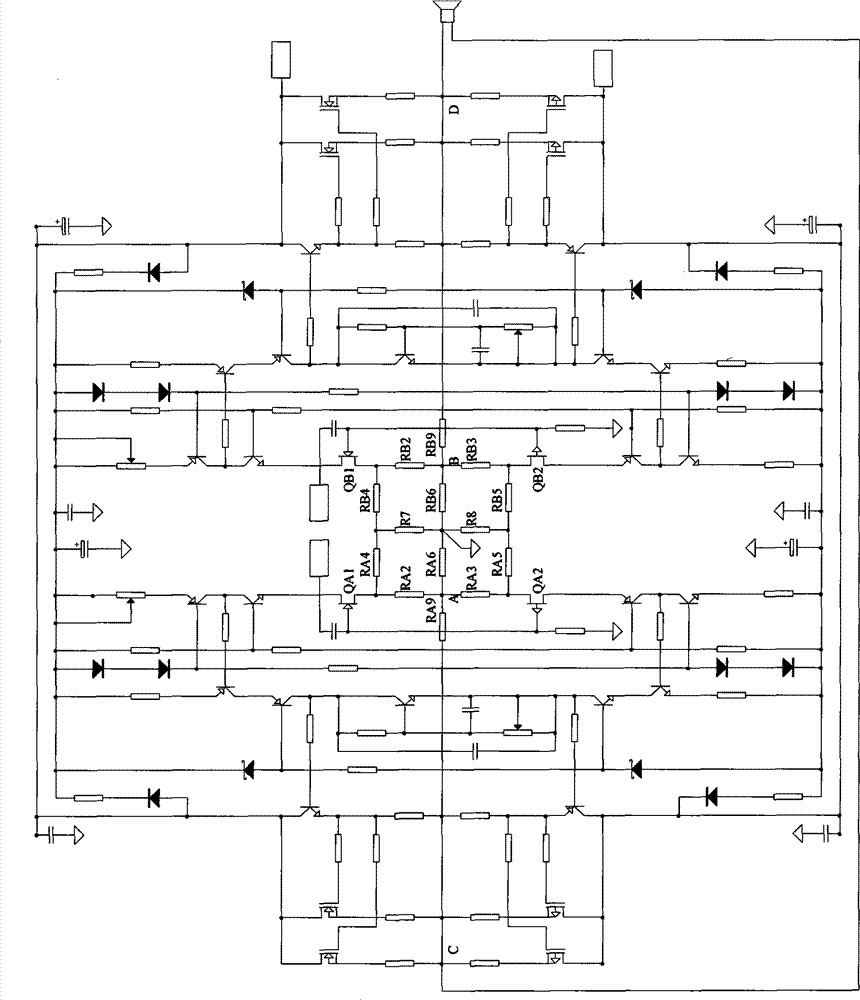
[0013] figure 1 , series feedback balanced high-fidelity audio amplifier circuit, all components are symmetrically connected with different polarities up and down, and symmetrically connected with the same polarity left and right. The sources of the four field effect input tubes QA1, QB1, QA2, and QB2 are respectively connected to the square resistor network RA2 , RB2, RA3, RB3, RA4, RB4, RA5, RB5, RA6, RB6, R7, R8 four corners, two loop feedback resistors RA9, RB9 are respectively connected to the square resistor network RA2, RB2, RA3, RB3, RA4, Midpoints A and B on one side of RB4, RA5, RB5, RA6, RB6, R7, and R8, that is, the midpoints A and B of the source resistance network of two upper and lower symmetrical field effect input transistors with opposite polarities on one side, and the other ends respectively Connect the middle points C and D of the output terminals on the same side of the amplifier circuit to form a fully symmetrical series negative feedback balance circuit...
Embodiment 2
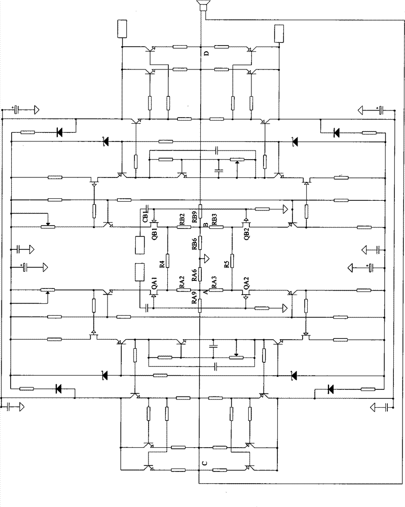
[0017] figure 2 , series feedback balanced high-fidelity audio amplifier circuit, all components are symmetrically connected with different polarities up and down, and symmetrically connected with the same polarity left and right. The sources of the four field effect input tubes QA1, QB1, QA2, and QB2 are respectively connected to the square resistor network RA2 , RB2, RA3, RB3, R4, R5, RA6, RB6 four corners, one end of two loop feedback resistors RA9, RB9 respectively connected to one side of the square resistor network RA2, RB2, RA3, RB3, R4, R5, RA6, RB6 The midpoints A and B, that is, the midpoints A and B of the source resistance network of two upper and lower symmetrical field effect input transistors with opposite polarities on one side, and the other ends are respectively connected to the midpoints C and D of the output terminals on the same side of the amplifying circuit, forming a complete left and right Symmetrical series negative feedback balance circuit structure...
Embodiment 3
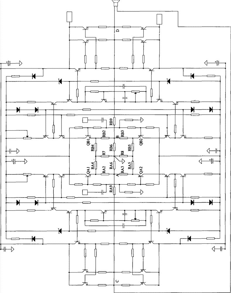
[0021] image 3 , series feedback balanced high-fidelity audio amplifier circuit, all components are symmetrically connected with different polarities up and down, symmetrically connected with the same polarity left and right, and the emitters of four bipolar triode input tubes QA1, QB1, QA2, QB2 are respectively connected to the square Four corners of resistor nets RA2, RB2, RA3, RB3, RA4, RB4, RA5, RB5, RA6, RB6, R7, R8, two loop feedback resistors RA9, RB9 are connected to square resistor nets RA2, RB2, RA3, RB3 respectively , RA4, RB4, RA5, RB5, RA6, RB6, R7, R8 side midpoints A, B, that is, two upper and lower opposite polarity symmetrical bipolar triode input tube emitter resistance network midpoint A, B, the other end is respectively connected to the middle points C and D of the output end of the same side of the amplifier circuit, forming a fully symmetrical series negative feedback balance circuit structure.
[0022] As a further preferred embodiment, the center poin...
PUM
 Abstract
Description
Claims
Application Information
 - R&D
- Intellectual Property
- Life Sciences
- Materials
- Tech Scout
- Unparalleled Data Quality
- Higher Quality Content
- 60% Fewer Hallucinations
Browse by: Latest US Patents, China's latest patents, Technical Efficacy Thesaurus, Application Domain, Technology Topic, Popular Technical Reports.
© 2025 PatSnap. All rights reserved.Legal|Privacy policy|Modern Slavery Act Transparency Statement|Sitemap|About US| Contact US: help@patsnap.com


