Structure of Working Chamber Components of Cryogenic Cylinder for Liquefied Natural Gas Evaporated Gas Compressor

A technology of liquefied natural gas and component structure, which is applied in the field of compressors, can solve problems such as poor casting performance, and achieve the effects of simple casting, good sealing and movement performance, and energy saving

Active Publication Date: 2017-04-26
XI AN JIAOTONG UNIV
View PDF4 Cites 2 Cited by
  • Summary
  • Abstract
  • Description
  • Claims
  • Application Information

AI Technical Summary

Problems solved by technology

However, the castability of the material is poor

Method used


Image

  • Structure of Working Chamber Components of Cryogenic Cylinder for Liquefied Natural Gas Evaporated Gas Compressor
  • Structure of Working Chamber Components of Cryogenic Cylinder for Liquefied Natural Gas Evaporated Gas Compressor
  • Structure of Working Chamber Components of Cryogenic Cylinder for Liquefied Natural Gas Evaporated Gas Compressor

Examples


Embodiment 1

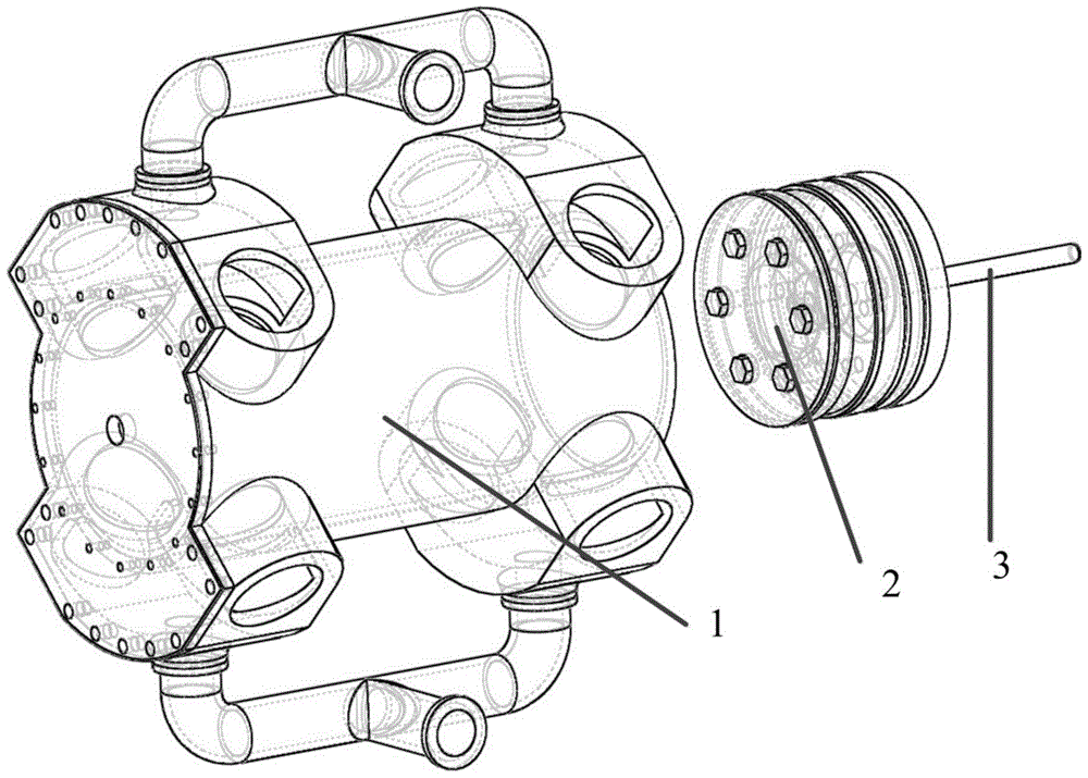
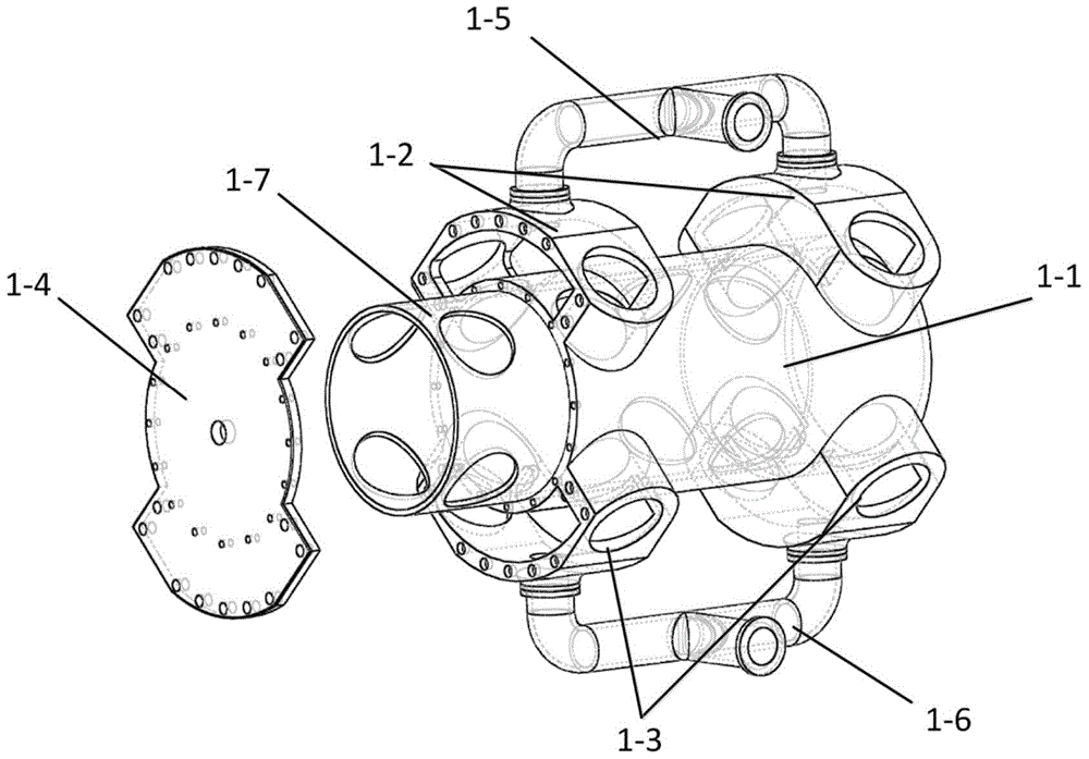
[0028] figure 2 The one-piece cast cylinder structure is shown, the cylinder body 1-1, the intake valve chamber 1-2 and the exhaust valve chamber 1-3 are integrally cast, the upper part of the cylinder is the intake valve chamber, and the lower part is the exhaust valve chamber. 8 in total. Wherein two valve chambers share an intake and exhaust channel, one side to the crankshaft is closed, the other end is half-opened so as to be cast, and the opening is sealed by the end cover 1-4. The front-end valve chamber is milled out a plane after the casting is completed, and a screw hole is provided on the plane, which is fastened with the end cover 1-4 with bolts. The inlet valve chamber 1-2 and the exhaust valve chamber 1-3 have flanges that can be connected to the flanges, and the flanges are respectively connected to the flanges of the intake manifold 1-5 and the exhaust manifold 1-6 through bolts connected. The air intake and collection air pipes 1-5 and the exhaust air coll...

Embodiment 2

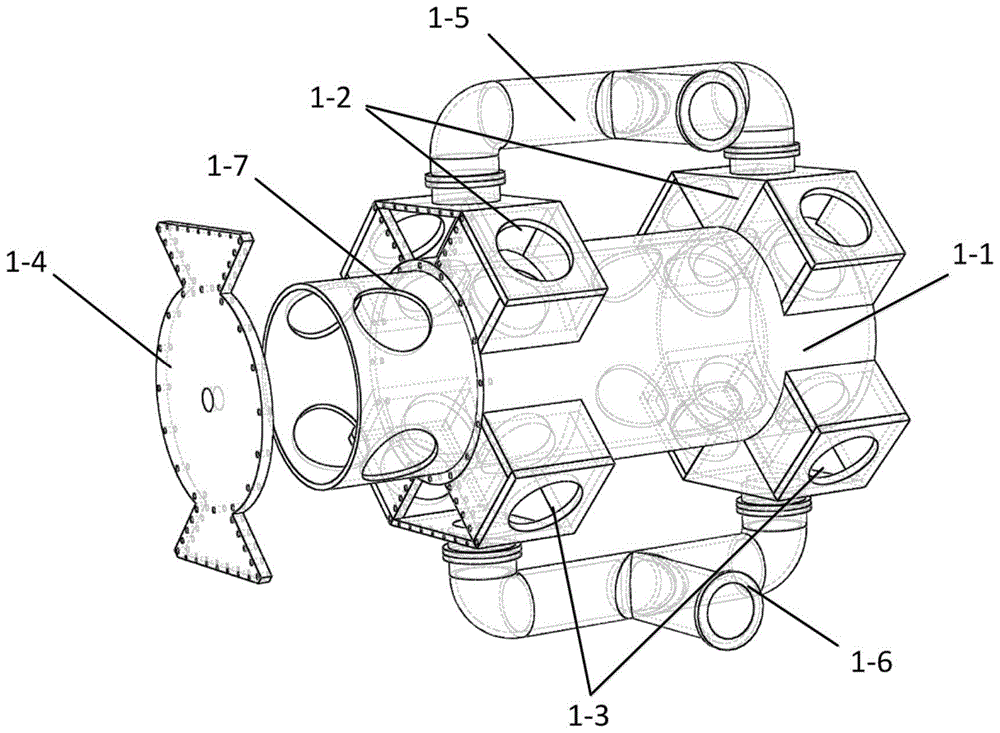
[0030] Such as image 3 As shown, the difference from Embodiment 1 is that the cylinder body 1-1, the intake valve chamber 1-2 and the exhaust valve chamber 1-3 of this embodiment are manufactured separately and connected by welding. The cylinder body 1-1 is only a cylindrical cavity, and the intake valve chamber 1-2 and the exhaust valve chamber 1-3 are welded together by several steel plates respectively. The combined shape of the valve housing is a cylindrical valve hole in a rectangular parallelepiped. All the other settings are similar to Embodiment 1, one side of the crankshaft is closed, the other end is half-opened for casting, and the opening is sealed by the end cover 1-4. Because the outer wall of the intake valve chamber 1-2 and the exhaust valve chamber 1-3 is a plane, several threads can be directly opened on the outer wall of the cylinder block 1-1, the intake valve chamber 1-2 and the exhaust valve chamber 1-3. The holes are connected to the end cover 1-4 by ...


PUM


Abstract

The invention discloses a low-temperature air cylinder working chamber component structure of a liquefied natural gas vapor compressor. The low-temperature air cylinder working chamber component structure of the liquefied natural gas vapor compressor comprises an air cylinder, a piston and a piston rod. A cylinder body of the air cylinder is of a single-wall cylinder type with two open ends, two air inflow valve cages located at the two ends of the cylinder body are arranged at the upper end of the cylinder body, and two air release valve cages located at the two ends of the cylinder body are arranged at the lower end of the cylinder body. According to the low-temperature air cylinder working chamber component structure of the liquefied natural gas vapor compressor, the air cylinder is of a single wall structure, the structure is simple, and casting is facilitated. The valve cages can be cast and formed together with the air cylinder body, and the valve cages can also be welded to the air cylinder by combining plurality of steel plates in a welding method. Due to the fact that the air cylinder body only has the single wall, heat conducted to an upper air suction part through an exhaust part with high temperature during operating can be reduced, inflowing air is effectively prevented from being heated, and more energy is saved in the compressing process. The outward ends of the air inflow valve cages and the outward ends of the air outflow valve cages are open, a plurality of fastening screw holes are formed, an air cylinder cover also serves as outer walls of the valve cages, bolts are used for fastening, and casting difficulty can be further lowered.

Description

technical field [0001] The invention belongs to the technical field of compressors, and in particular relates to an assembly structure of a low-temperature cylinder working chamber of a liquefied natural gas vapor compressor. Background technique [0002] The liquefied natural gas boil-off gas (BOG) compressor is used to compress the boil-off gas generated during the storage and transportation of liquefied natural gas, and its primary cylinder needs to withstand a low temperature of about -160°C. There are mainly two types of cylinders on the market: one is the vertical labyrinth sealed structure produced by Switzerland's Sulzer-Burkhard Company, and the material is GGG Ni35 ductile iron. The other is a horizontal counter-moving compressor produced by Japan's Ishikawa Island Harima (IHI), which uses a non-metallic piston ring to seal. Cylinder, piston and other materials are stainless steel. [0003] 20Mn32AL is a low-temperature steel developed by my country itself, which...

Claims


Application Information

Patent Timeline
Patent Type & Authority Patents(China)
IPC IPC(8): F04B37/12F04B39/12F04B39/00F04B39/10
Inventor 李云郁永章燕翌
Owner XI AN JIAOTONG UNIV
Why Eureka
Try Eureka