
Coal pyrolysis equipment

A technology of coal pyrolysis and equipment, which is applied in special forms of dry distillation, gas dust removal, petroleum industry, etc., and can solve the problems of low degree of automation, energy waste, and low dust removal efficiency

Inactive Publication Date: 2015-07-01
HENAN DRAGON INTO COAL TECH CO LTD
View PDF4 Cites 0 Cited by
  • Summary
  • Abstract
  • Description
  • Claims
  • Application Information

AI Technical Summary

Problems solved by technology

However, the current coal pyrolysis equipment still has various problems, such as low dust removal efficiency and low degree of automation, which is actually a waste of energy

Method used


Image

  • Coal pyrolysis equipment
  • Coal pyrolysis equipment

Examples


Embodiment Construction

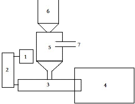
[0016] Such as figure 1 As shown, the motor 1 drives the reduction gearbox 2 to provide power for the whole device. The reduction gearbox drives the screw feeder 3 to transport the coal to the coal pyrolysis device 4 . The coal pyrolysis device 4 pyrolyzes the coal, and the generated gas enters the dust remover 5 and contacts with the dust removal particles supplied by the dust removal particle supply device 6, thereby removing dust pollutants in the gas. Coal ash is used for dust removal particles, and the cleaned gas is discharged through the conveying pipeline 7, while the dust removal particles after absorbing dust enter the screw feeder 3 and enter the coal pyrolysis device 4 again. The dust collector 5 is a moving bed dust collector.


PUM


Abstract

The invention discloses coal pyrolysis equipment. The equipment comprises a coal pyrolysis device used for performing pyrolysis on coal, a coal conveying device used for conveying coal to the coal pyrolysis device, a power source used for providing power to the coal conveying device, a pyrolysis gas dust collection device used for collecting dust for gas after coal pyrolysis, and a dust-removing particle supply device used for supplying dust-removing particle supply device to the pyrolysis dust-collection device. The coal pyrolysis equipment has high utilization of dust-removing particles.

Description

technical field [0001] The invention relates to coal pyrolysis equipment, which belongs to the field of coal powder pyrolysis. Background technique [0002] Coal is one of the important energy sources in our country. As far as my country's proven primary energy reserves are concerned, my country is short of oil and gas, but relatively rich in coal resources. Although my country's coal energy reserves are abundant, according to the current use conditions, the pollution caused by the use of coal is a fact that cannot be ignored. Therefore, coal will still be used as the main energy source in our country, and the current smog weather across the country requires us to use coal energy cleanly. [0003] In order to reduce the pollution of coal energy utilization, many coal pyrolysis equipments have appeared. However, the current coal pyrolysis equipment still has various problems, such as low dust removal efficiency and low degree of automation, which is actually a waste of ene...

Claims


Application Information

Patent Timeline
Patent Type & Authority Applications(China)
IPC IPC(8): C10B53/04
CPCC10B53/04C10B57/00C10K1/02
Inventor 朱书成
Owner HENAN DRAGON INTO COAL TECH CO LTD
Learn More