
Frame cross member welding

A frame beam and welding technology, applied in the field of fixed frames, can solve problems such as hidden safety hazards, difficult installation and maintenance, etc., and achieve the effect of solving hidden safety hazards and difficult installation and maintenance

Inactive Publication Date: 2015-07-01
ZHUCHENG CITY FURI MACHINERY
View PDF0 Cites 3 Cited by
  • Summary
  • Abstract
  • Description
  • Claims
  • Application Information

AI Technical Summary

Problems solved by technology

[0003] The purpose of the present invention is to provide an assembly frame that can reasonably install the flameout motor mounting plate, steering oil pipe, water tank support rod, horn bracket, etc., to solve the problems of difficult installation and maintenance and potential safety hazards

Method used


Image

  • Frame cross member welding
  • Frame cross member welding

Examples


Embodiment Construction

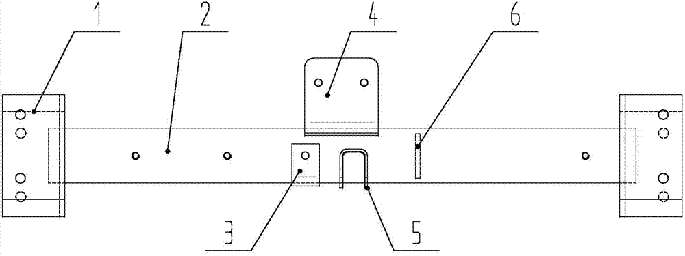
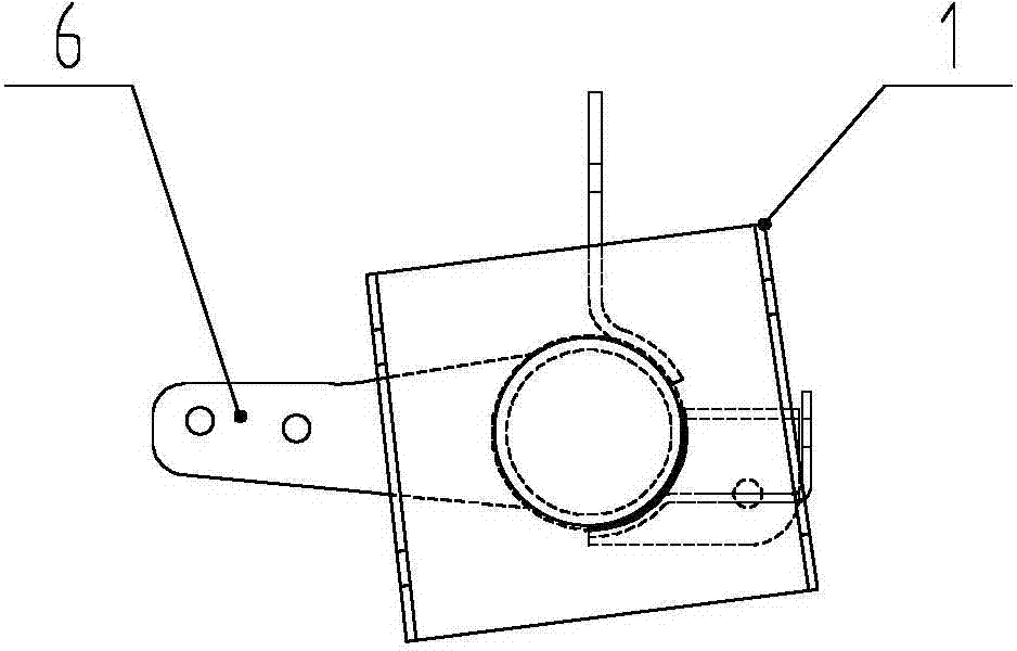
[0010] like figure 1 , 2 As shown, the present invention includes a beam tube 2, which is characterized in that a beam fixing plate 1 is provided at both ends of the beam tube 2, a flameout motor mounting plate 4 is provided above the middle of the beam tube 2, and a flameout motor mounting plate 4 is shown The front side of the lower left crossbeam tube 2 is provided with a steering tubing bracket 3, the right side of the steering tubing bracket 3 is provided with a water tank strut bracket 5, and the right side of the water tank strut bracket 5 is provided with a horn bracket 6 on the rear side of the crossbeam tube 2 .


PUM


Abstract

The invention discloses frame cross member welding. The frame cross member welding comprises a cross member pipe. The cross member pipe is characterized in that the two ends of the cross member pipe are provided with cross member fixing plates, a flameout motor installing plate is arranged above the middle of the cross member pipe, a steering oil pipe support is arranged at the front side of the cross member pipe of the left lower portion of the flameout motor installing plate, a water tank bracing support is arranged at the right side of the steering oil pipe support, and a horn support is arranged at the rear side of the cross member pipe at the right side of the water tank bracing support. The frame cross member welding has the advantages that the flameout motor installing plate, a steering oil pipe, a water tank bracing and the horn support are installed on an assembly frame reasonably, and the problems that the installation and the maintenance are difficult, and the potential safety hazard exists are solved.

Description

technical field [0001] The invention relates to a fixing frame, in particular to a vehicle frame beam welding. Background technique [0002] At present, some parts of automobiles are scattered and installed, such as the flameout motor mounting plate, steering oil pipe, water tank support rod, horn bracket, etc., involving messy installation of circuits and oil circuits, difficult installation, troublesome maintenance, and easy to cause safety hazards. Contents of the invention [0003] The purpose of the present invention is to provide an assembly frame that can rationally install the flame-out motor mounting plate, steering oil pipe, water tank brace, horn bracket, etc., to solve the problems of difficult installation and maintenance and potential safety hazards. [0004] In order to achieve the above object, the technical solution of the present invention includes a beam tube, which is characterized in that the two ends of the beam tube are provided with a beam fixing pl...

Claims


Application Information

Patent Timeline
Patent Type & Authority Applications(China)
IPC IPC(8): B62D21/00
CPCB62D21/09
Inventor 解会军
Owner ZHUCHENG CITY FURI MACHINERY
Learn More