Automatic runoff and sediment monitor water inlet siphon type regulating device
A technology for regulating devices and water inlets, which is applied in the direction of measuring devices, test water, sampling devices, etc., can solve problems such as low precision, labor and manpower consumption, sedimentation, etc., and achieve accurate sampling, uniform water samples, and abundant water flow Effect
- Summary
- Abstract
- Description
- Claims
- Application Information
AI Technical Summary
Problems solved by technology
Method used
Image
Examples
Embodiment 1
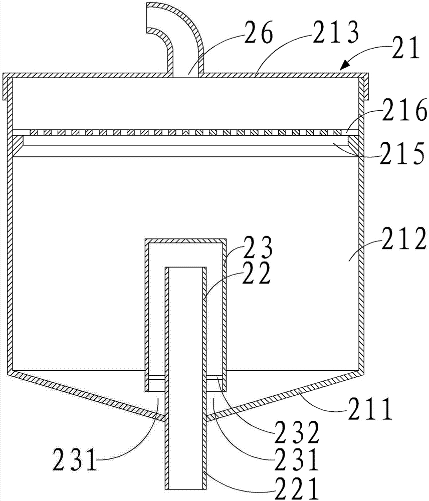
[0027] Embodiment one, as attached figure 1 As shown, a siphon type adjustment device for the water inlet of an automatic runoff sediment monitor includes a water storage tank 21 and a siphon tube arranged at the bottom of the water storage tank 21, the water inlet of the siphon tube is located at the bottom of the water storage tank 21, and the bottom of the water storage tank 21 The wall is in the shape of a funnel or a spherical crown, and a water inlet 26 is arranged on the top of the water storage tank 21 .
[0028] The upper part of the water storage tank is used to enter the water. The impact of the water flow will keep the water flow in the water storage tank in a flowing state to avoid sedimentation. The siphon can make the sampled water flow stable and accurate, which is conducive to the accuracy of soil erosion monitoring data and get more results. Basic data for science.
[0029] The water storage tank 21 includes a bottom plate 211, a cylinder wall 212 and a top ...
Embodiment 2
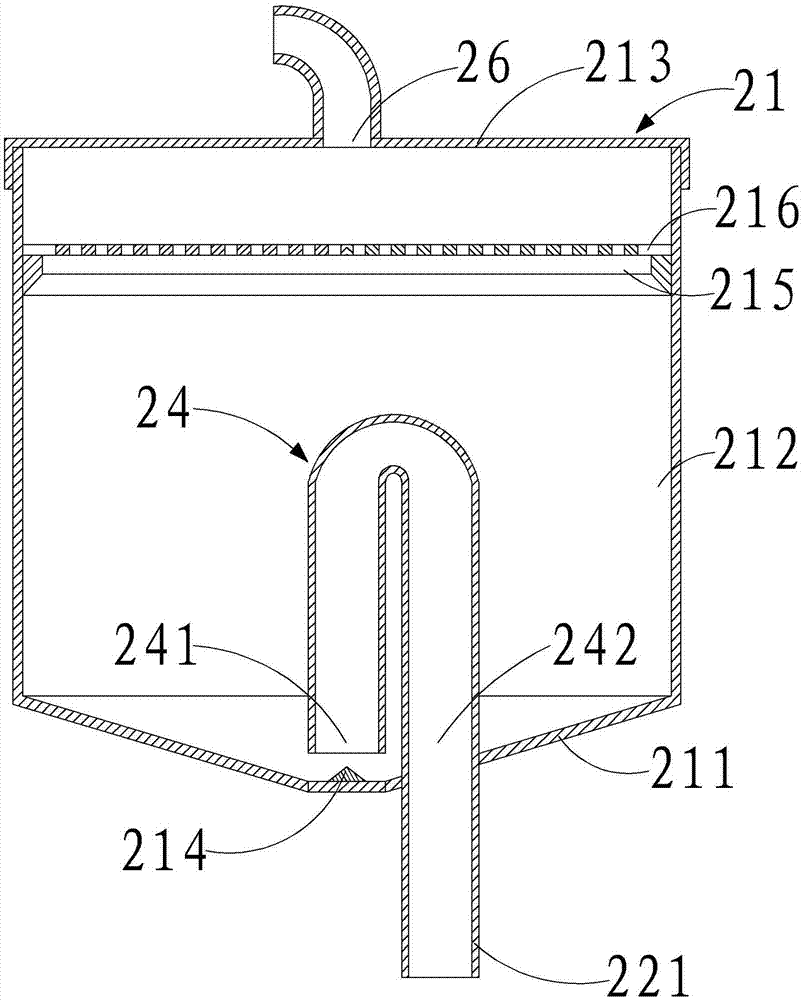
[0033] Embodiment two, as attached figure 2 As shown, the siphon includes a U-shaped pipe 24 fixedly arranged on the bottom plate 211, and the two free ends of the U-shaped pipe 24 are respectively a first branch pipe 241 and a second branch pipe 242, and the first branch pipe 241 and the cone Corresponding to the small opening of the tubular bottom plate 211, the small opening of the tapered tubular bottom plate 211 is closed, the second branch pipe 242 extends downward through the bottom plate 211 to form a downspout 221, and a return pipe 221 is formed between the first branch pipe 241 and the bottom plate 211. Shuikou 231.
[0034] The inverted U-shaped tube can also realize siphon suction flow. The nozzle of the first branch tube 241 and the bottom plate 211 form a water return port 231, and the water sample is sucked out of the water storage tank. When the rainfall is small, the water storage tank stores water and reaches the top of the U-shaped tube. After that, it wi...
Embodiment 3
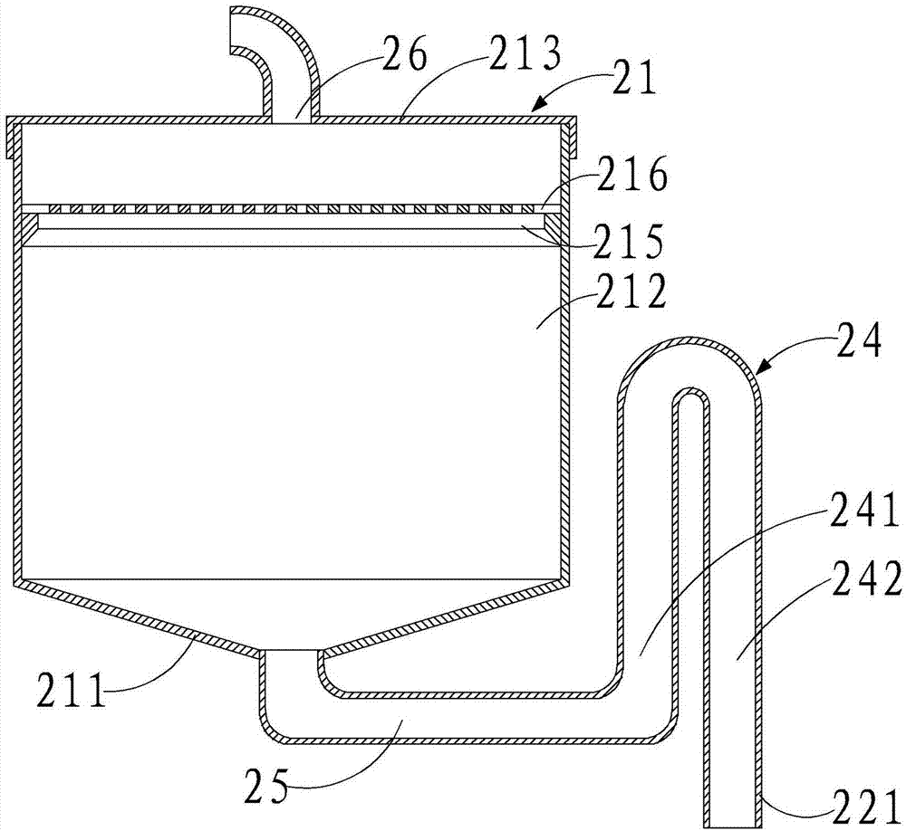
[0037] Embodiment three, as attached image 3 As shown, the siphon includes a water diversion pipe 25 communicated with the small opening of the tapered tubular bottom plate 211 and a U-shaped pipe 24 communicated with the other end of the water diversion pipe 25, and the two free ends of the U-shaped pipe 24 are respectively the first branch pipe 241 and a second branch pipe 242 , the first branch pipe 241 communicates with the water diversion pipe 25 , and the second branch pipe 242 extends downward to form the downpipe 221 .
[0038] The water diversion pipe 25 leads the sampling water to the nozzle of the first branch pipe 241. After the water level reaches the top of the U-shaped pipe, it will flow into the second branch pipe 242. The water in the water storage tank has no precipitation, and the sampling is uniform. After the siphon is formed, the water sample will evenly flow into the monitoring mechanism.
[0039]The top wall 213 is buckled on the top of the cylinder w...
PUM
 Abstract
Description
Claims
Application Information
 - R&D
- Intellectual Property
- Life Sciences
- Materials
- Tech Scout
- Unparalleled Data Quality
- Higher Quality Content
- 60% Fewer Hallucinations
Browse by: Latest US Patents, China's latest patents, Technical Efficacy Thesaurus, Application Domain, Technology Topic, Popular Technical Reports.
© 2025 PatSnap. All rights reserved.Legal|Privacy policy|Modern Slavery Act Transparency Statement|Sitemap|About US| Contact US: help@patsnap.com


