
Novel detection method of optical fiber gyroscope

A technology of fiber optic gyroscope and single-mode fiber, which is applied in the field of communication, can solve the problems of data zero bias fluctuation and zero bias stability reduction, etc.

Inactive Publication Date: 2015-06-24
GUANGXI UNIV
View PDF6 Cites 9 Cited by
  • Summary
  • Abstract
  • Description
  • Claims
  • Application Information

AI Technical Summary

Problems solved by technology

[0031] However, in the existing angular velocity measurement methods, the existing Faraday magnetic field effect, drift or other low-frequency noise caused by temperature fluctuations, as well as the polarization evolution in the fiber optic gyroscope and the flicker noise of the detector will lead to fluctuations in the zero bias of the data That is, the bias stability is reduced

Method used


Image

  • Novel detection method of optical fiber gyroscope
  • Novel detection method of optical fiber gyroscope
  • Novel detection method of optical fiber gyroscope

Examples


Embodiment Construction

[0058] In the following description, for purposes of explanation, numerous specific details are set forth in order to provide a thorough understanding of one or more embodiments. It may be evident, however, that these embodiments may be practiced without these specific details. In other instances, well-known structures and devices are shown in block diagram form in order to facilitate describing one or more embodiments.

[0059] Various embodiments according to the present invention will be described in detail below with reference to the accompanying drawings.

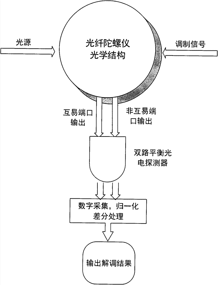
[0060] image 3 A schematic diagram of the method in the present invention is shown. Such as image 3 As shown, the interferometric depolarized fiber optic gyroscope is phase-modulated with a sinusoidal signal. When measuring, the reciprocal port (I port) and the non-reciprocal port (II port) of the fiber optic gyroscope are simultaneously detected by a dual-way balanced photodetector. mouth), the digital acquisiti...


PUM


Abstract

The present invention provides a novel detection method of an optical fiber gyroscope, wherein the detection ports are a reciprocal port (I port) and a nonreciprocal port (II port) of an interferometric depolarization fiber optic gyroscope, and the signal processing adopts the differential signal processing manner. The method comprises that: the optical structure of the interferometric depolarization fiber optic gyroscope for testing requires that lyot depolarizers are respectively added between the light source and the light source coupler, the light source coupler and the optical fiber ring coupler, and the optical fiber ring coupler and the optical fiber ring, the phase modulation adopts the sine signal having optical fiber gyroscope eigenfrequency, the amplitude of the sine signal is correspondingly adjusted so as to make the modulation depth value be stabilized to near 1.841, a dual-channel photoelectrically balanced detector is utilized to concurrently detect the reciprocal port (I port) and the nonreciprocal port (II port) of the interferometric depolarization fiber optic gyroscope, the two electrical signals being subjected to photoelectric conversion are subjected to normalization and then are subjected to a differential treatment, and the differential result is utilized to demodulate the gyroscope signal. With the method of the present invention, the random walk of the optical fiber gyroscope can be effectively reduced, and the zero-bias stability of the optical fiber gyroscope can be improved.

Description

technical field [0001] The present invention relates to the field of communication technology, and more specifically, to a dual-channel balanced differential detection principle and device of an interferometric depolarized fiber optic gyroscope. Background technique [0002] A gyroscope is a rotational sensor used to measure the rotational angular velocity of the carrier on which it is mounted. Gyroscopes are widely used in the guidance of aircraft and weapons, precision measurement in industry and military, and other fields. There are three types of common gyroscopes: mechanical gyroscopes, laser gyroscopes, and fiber-optic gyroscopes (Fiber-optic gyroscope, FOG). The mechanical gyroscope is an orientation device manufactured by using the physical principle that the rotating shaft of a high-speed rotating body has a tendency to maintain its direction. Because the mechanical gyroscope contains moving parts, its structure is complex, the process requirements are high, and th...

Claims


Application Information

Patent Timeline
IPC IPC(8): G01C19/72
CPCG01C19/72
Inventor 赵大宇张振荣
Owner GUANGXI UNIV
Learn More