Circuit for contactor type double-power-supply changeover switching appliance
A technology of dual power conversion and switching electrical appliances, applied in circuit devices, emergency power supply arrangements, electrical components, etc., can solve the problems of unsatisfactory mechanical interlock reliability, unsatisfactory use requirements, slow conversion speed, etc., and achieve power saving effect. Obvious, great promotion value, close power factor effect
- Summary
- Abstract
- Description
- Claims
- Application Information
AI Technical Summary
Problems solved by technology
Method used
Image
Examples
Embodiment 1
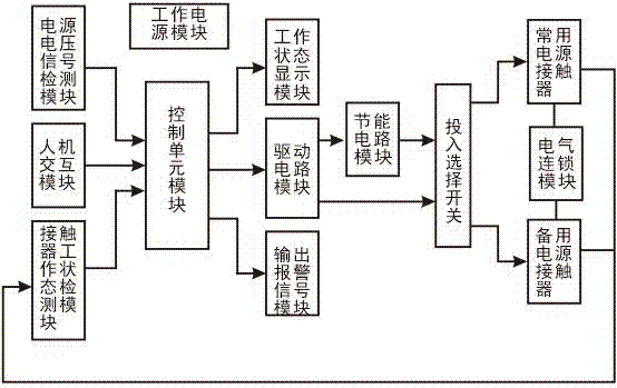
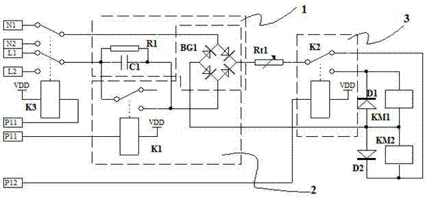
[0041] Embodiment 1: see figure 1 ~ figure 2 , the circuit used for the contactor-type dual power supply switching electrical appliances includes two AC contactors as the normal power switch and the backup power switch, and a control circuit for controlling the operation of the two AC contactors; The contactor is defined as a common contactor KM2, and the AC contactor installed at the switch end of the standby power supply is defined as a standby contactor KM1; the control circuit includes a working power supply module for supplying power to the system circuit, which is used as a control unit module for central data processing. The power supply voltage signal detection module, human-computer interaction module, and contactor working state detection module connected to the input end of the control unit module, and the working state display module, output alarm signal module, and control subsequent energy-saving circuit module respectively connected to the output end of the co...
Embodiment 2
[0048] Example 2: see figure 2 , this embodiment is basically the same as Embodiment 1, the difference lies in the capacity of the main switch contact: Specifically, for the ATSE whose main switch contact is 16A~25A, the CJT1 series AC contact with a rated current of 9A~12A can be selected If the working voltage is 220V: the non-polar capacitor C1 can choose a CBB capacitor with a withstand voltage of 400V and a capacity of 0.47uF; or a safety capacitor with a withstand voltage of 240V and a capacity of 0.47uF to match it The discharge resistor R1 is 750kΩ. If the working voltage is 380V: the non-polar capacitor C1 can be a CBB capacitor with a withstand voltage of 630V and a capacity of 0.22uF; or a safety capacitor with a withstand voltage of 400V and a capacity of 0.22uF, matching the discharge resistor R1 is 500kΩ.
PUM
 Abstract
Description
Claims
Application Information
 - Generate Ideas
- Intellectual Property
- Life Sciences
- Materials
- Tech Scout
- Unparalleled Data Quality
- Higher Quality Content
- 60% Fewer Hallucinations
Browse by: Latest US Patents, China's latest patents, Technical Efficacy Thesaurus, Application Domain, Technology Topic, Popular Technical Reports.
© 2025 PatSnap. All rights reserved.Legal|Privacy policy|Modern Slavery Act Transparency Statement|Sitemap|About US| Contact US: help@patsnap.com


