
Fuel cell system having ejector

A fuel cell system and injector technology, used in fuel cells, fuel cell additives, fuel cell components, etc., can solve problems such as blockage, cell stack deterioration, and fuel gas supply rate reduction, and increase cycle efficiency. , The effect of reducing output deterioration and preventing oversupply

Active Publication Date: 2015-06-17
HYUNDAI MOTOR CO LTD
View PDF3 Cites 2 Cited by
  • Summary
  • Abstract
  • Description
  • Claims
  • Application Information

AI Technical Summary

Problems solved by technology

In this case, condensed water in a liquid state contained in the circulating fuel gas may be directly supplied to the battery stack, causing droplets of the condensed water to clog a part of the channels of the battery stack
Therefore, if a part of the channel of the cell stack is blocked, the fuel gas supply rate to the channel part decreases, and the entire cell stack may deteriorate

Method used


Image

  • Fuel cell system having ejector
  • Fuel cell system having ejector
  • Fuel cell system having ejector

Examples


Embodiment Construction

[0026] Exemplary embodiments of the present invention will hereinafter be described in detail with reference to the accompanying drawings.

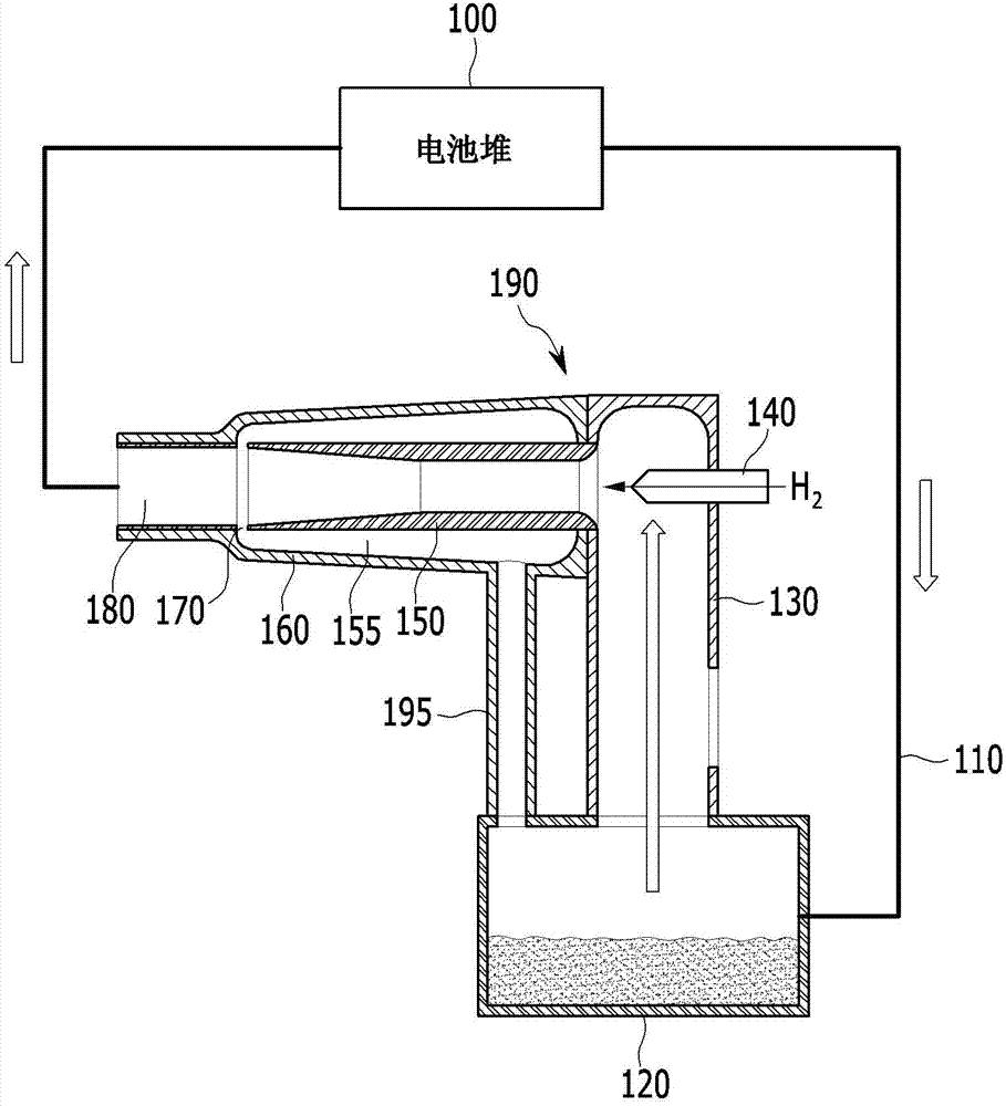
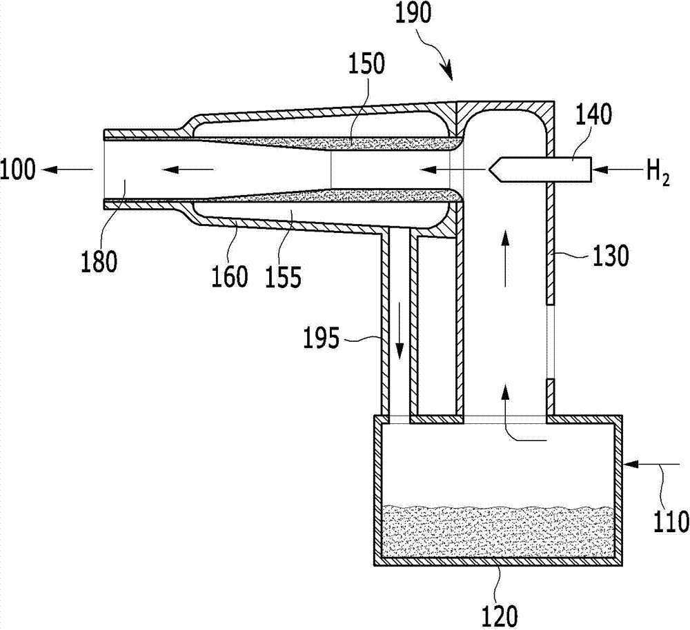
[0027] figure 1 A schematic diagram showing a fuel cell system according to an exemplary embodiment of the present invention. refer to figure 1 , the fuel cell system includes a cell stack 100 , a fuel gas circulation pipeline 110 , a condensed water accumulator 120 , and an injector 190 . The injector 190 includes a vacuum suction pipe 130 , a fuel gas nozzle 140 , an inner casing 150 , an outer casing 160 , and a condensed water drain pipe 195 .

[0028] The fuel gas is circulated to the cell stack 100 through the condensed water accumulator 120 arranged on the fuel gas circulation line 110, the vacuum suction pipe 130 and the inner case 150, and the outlet 180 of the injector 190, and the cell stack 100 is supplied to the Fuel gas and air (given without reference numerals) therein generate electrical energy. In an exemplary embodim...


PUM


Abstract

A fuel cell system having an ejector includes a stack for generating electricity by using air and fuel gas being supplied thereto. A fuel gas circulating line re-circulates the fuel gas from an outlet of the stack to an inlet of the stack. An ejector is mounted to the fuel gas circulating line for supplying fresh fuel gas and circulating the fuel gas. The ejector includes a vacuum suction pipe having one side connected to the fuel gas re-circulating line and a fuel gas spray nozzle mounted to the vacuum suction pipe for spraying the fuel gas to form a vacuum. An inner housing through which the fuel gas sprayed from the fuel gas spray nozzle passes. An outer housing is arranged on an outside of the inner housing to construct a condensed water space with the inner housing. The inner housing drains water from an inside of the inner housing to the condensed water space.

Description

[0001] Cross References to Related Applications [0002] This application claims priority to Korean Patent Application No. 10-2013-0157584 filed with the Korean Intellectual Property Office on December 17, 2013, the entire contents of which are incorporated herein by reference. technical field [0003] The present invention relates to a fuel cell system having an injector that stably supplies fuel gas and moisture to a cell stack that generates electricity by using the fuel gas and air for stably generating electricity. Background technique [0004] As is well known, a fuel cell vehicle having a fuel cell system installed therein supplies hydrogen used as fuel to a fuel cell stack to generate electric power to drive a motor driving the vehicle. In this case, the fuel cell system is an electrical system in which the chemical energy of the fuel is not converted into heat through combustion, but the electrochemical energy is directly converted into electrical energy within the ...

Claims


Application Information

Patent Timeline
Patent Type & Authority Applications(China)
IPC IPC(8): H01M8/02H01M8/04
CPCH01M8/04097H01M8/04164H01M2250/20H01M8/04201H01M2220/20Y02E60/10Y02E60/50H01M8/04156H01M8/04179
Inventor 郑世权鲁容奎
Owner HYUNDAI MOTOR CO LTD
Learn More