
Pressure reduction and water drainage system under ultra-deep underground space structure bottom plate

A space structure and drainage system technology, applied in infrastructure engineering, protective devices, buildings, etc., can solve the problems of large project costs, high structural crack resistance, and high fatigue resistance requirements, and achieve high work efficiency and good anti-floating effect , The effect of low engineering cost

Inactive Publication Date: 2015-06-17
ZHONGCHUAN NO 9 DESIGN & RES INST
View PDF6 Cites 4 Cited by
  • Summary
  • Abstract
  • Description
  • Claims
  • Application Information

AI Technical Summary

Problems solved by technology

[0003] At present, the anti-floating measures in underground engineering are mainly to install anti-floating anchors and anti-floating piles under the floor, and to balance the buoyancy of groundwater by increasing the overlying weight of the underground structure or setting anti-floating anchors and anti-lift piles. The strength is reasonable, and the later maintenance is simple and convenient, but the engineering cost is relatively large, and the requirements for crack resistance and fatigue resistance of the structure are high

Method used


Image

  • Pressure reduction and water drainage system under ultra-deep underground space structure bottom plate
  • Pressure reduction and water drainage system under ultra-deep underground space structure bottom plate
  • Pressure reduction and water drainage system under ultra-deep underground space structure bottom plate

Examples


Embodiment Construction

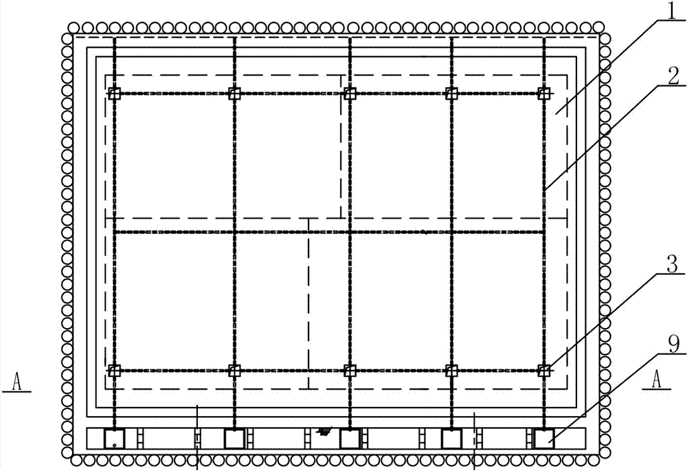
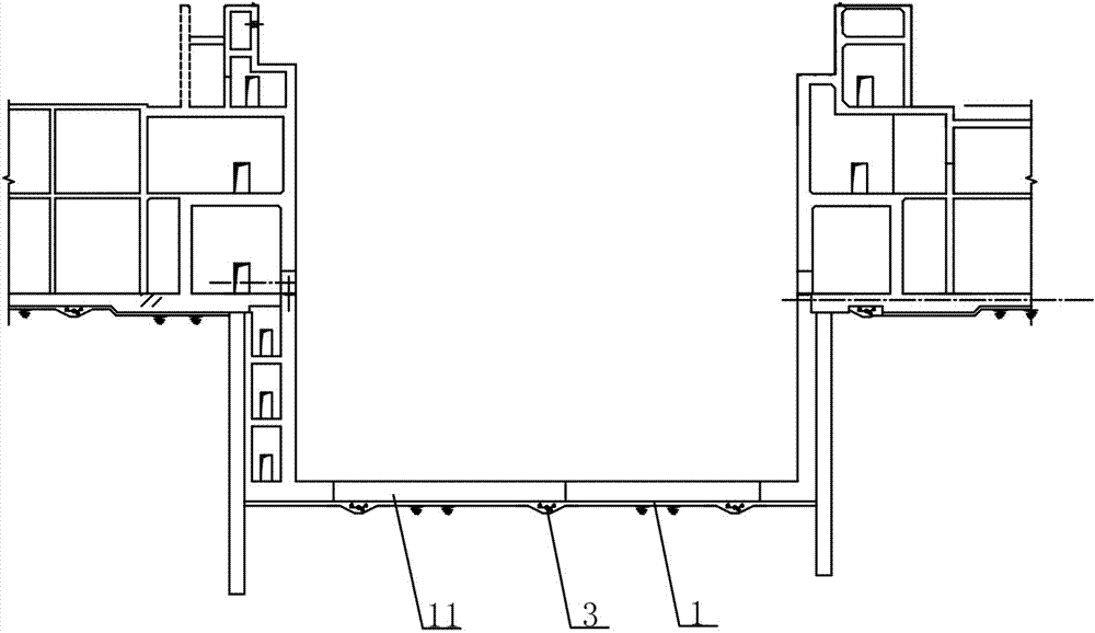
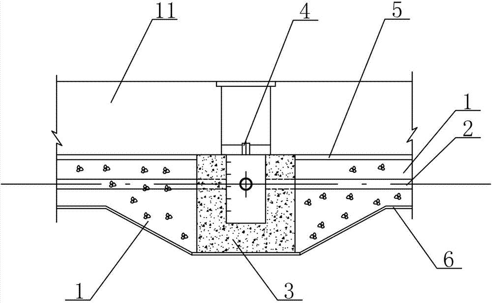
[0015] See attached figure 1 ~ attached figure 2 , the present invention consists of a gravel filter layer 1 arranged under the structural bottom plate 11, a drainage pipe 2, a water collection well 3 and a water pumping well 9. A steel pipe filled with water inlet holes 8, and several drainage pipes 2 are connected vertically and horizontally to form a grid-like drainage pipe network; the water collection well 3 is arranged at the nodes of the drainage pipes 2 connected vertically and horizontally on the outside; the pumping well 9 is arranged at One side of the drainage pipe network corresponds to the water collection well 3 one by one. The pumping well 9 is connected with the water collection well 3 by the drainage pipe 2. 9 Pump out the drain network.

[0016] See attached image 3 , the water collection well 3 is arranged at the node where the drainage pipes 2 are connected vertically and horizontally in the gravel filter layer 1, and the cover plate of the water coll...


PUM


Abstract

The invention discloses a pressure reduction and water drainage system under an ultra-deep underground space structure bottom plate. The pressure reduction and water drainage system is characterized by being composed of an inverted filter, water drainage pipes, water collection wells and pumping wells, the inverted filter, the water drainage pipes, the water collection wells and the pumping wells are arranged below the bottom plate, and the water drainage pipes form a mesh-shaped water drainage pipe network through a plurality of steel pipes provided with small holes; the water collection wells are arranged at the joints of the water drainage pipes which are longitudinally and transversely intersected; the pumping wells are arranged outside the water drainage pipes and communicated with the water collection wells; underground water is converged to the water collection wells from the drainage pipes in the inverted filter and is pumped out through the pumping wells. Compared with the prior art, the requirement for the anti-crack performance of the bottom plate is low, the pressure reduction effect and the anti-floating effect are good, the surrounding ground surface settlement can be effectively controlled while the bottom plate meets the anti-floating requirement, the number of anti-floating piles which are arranged is greatly decreased, the structure is simple, construction is convenient, the engineering cost is low, and the pressure reduction and water drainage system is particularly suitable for the anti-floating design of an underground space structure which is 30 m deep.

Description

technical field [0001] The invention relates to the field of underground structure anti-floating technology, in particular to a decompression drainage system under the floor of an ultra-deep underground space structure. Background technique [0002] With the acceleration of urbanization, the development of underground space has been paid more and more attention. For underground buildings such as large-scale underground shopping malls and underground parking garages, the buoyancy of the basement floor due to the penetration of groundwater and surface water has become an engineering project. focus in design. [0003] At present, the anti-floating measures in underground engineering are mainly to install anti-floating anchors and anti-floating piles under the floor, and to balance the buoyancy of groundwater by increasing the overlying weight of the underground structure or setting anti-floating anchors and anti-lift piles. The strength is reasonable, and the later maintenance...

Claims


Application Information

Patent Timeline
Patent Type & Authority Applications(China)
IPC IPC(8): E02D31/12
CPCE02D31/12
Inventor 李华梅袁坚李昀吴昊王勇徐剑徐永春林靖汪贵平
Owner ZHONGCHUAN NO 9 DESIGN & RES INST
Learn More