Eureka AIR delivers breakthrough ideas for toughest innovation challenges, trusted by R&D personnel around the world.

Welding device for internally-clad stainless steel tube of clad steel plate

A technology for stainless steel pipes and clad steel plates, applied in welding equipment, arc welding equipment, manufacturing tools, etc., can solve the problem of poor performance of stainless steel welds, unqualified corrosion resistance of inner clad stainless steel welds, unqualified corrosion resistance, etc. problems, to achieve the effect of excellent corrosion resistance, improved welding quality and production efficiency

Inactive Publication Date: 2015-06-17
WUXI QINENG WELDING EQUIP
View PDF6 Cites 2 Cited by
  • Summary
  • Abstract
  • Description
  • Claims
  • Application Information

AI Technical Summary

Problems solved by technology

The problem is that the welding head is welded with dissimilar steel, and it can only be welded from the outer surface of the pipe, resulting in unqualified corrosion resistance of the inner stainless steel weld
[0004] For the welding of internally clad stainless steel straight seam welded pipes, it is generally believed that internally clad stainless steel pipes cannot be formed by one-time welding. The weld seam is welded first, and the outer layer of carbon steel is welded later. The welding heat affects the first weld seam, which deteriorates the performance of the stainless steel weld seam and causes unqualified corrosion resistance.

Method used


Image

  • Welding device for internally-clad stainless steel tube of clad steel plate

Examples


Embodiment Construction

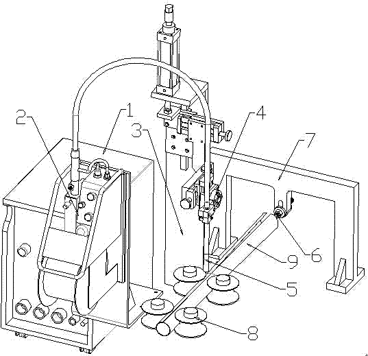
[0009] The specific embodiments of the present invention will be described with reference to the drawings, such as figure 1 As shown, the welding device for the stainless steel pipe in the composite steel plate includes MIG welding power source 1, automatic wire feeder 2, welding torch support 3, three-dimensional gun holder 4, MIG welding torch 5, welding tool 6, welding support 7, and sizing roll 8; The MIG welding gun 5 is installed on the three-dimensional gun frame 4 through the gun clamp, the three-dimensional gun frame 4 is installed on the welding gun holder 3, the sizing roller 8 is installed below the MIG welding gun 5, and the welding tool 6 The welding tool installed between the rollers of the sizing roller 8 6 One end is installed on the welding support 7, and the steel pipe 9 to be welded enters the welding tool 6 from the straight seam pipe production line, and enters between the sizing rollers 8, and the MIG The welding gun 5 is welding.

[0010] In the ordinary ...


PUM


Abstract

The invention relates to welding equipment, in particular to a welding device for an internally-clad stainless steel tube of a clad steel plate. The welding device comprises an MIG welding power source, an automatic wire feeder and an MIG welding gun. The MIG welding gun is mounted on a three-dimensional gun rack through a gun clamp, and the three-dimensional gun rack is mounted on a welding gun support. Sizing rolls are mounted below the MIG welding gun, and a welding fixture is mounted between the sizing rolls. One end of the welding fixture is mounted on a welding support, a steel tube to be welded enters the welding fixture from a straight-seam tube manufacturing production line and enters the position between the sizing rolls, and the steel tube is welded by the MIG welding gun. The welding device for the inner composite stainless steel tube of the clad steel plate is in butt joint with a common straight-seam tube manufacturing production line or a spiral tube manufacturing production line, open arc automatic welding is conducted from the outer surface of the steel tube, one-time welding is achieved, and the welding quality and the production efficiency are improved. Weld joint single-face welding and double-face forming of dissimilar metal welding are achieved. The quality of a welding joint is improved, particularly, the weld microstructure of a stainless steel composite layer face achieves two-phase organization, and therefore the corrosion resistance is better than that of a base material.

Description

Technical field [0001] The invention relates to a welding equipment, in particular to a welding device for a stainless steel tube inside a composite steel plate. Background technique [0002] At present, domestic carbon steel-stainless steel clad steel plate has been mass-produced. The clad steel plate is covered with stainless steel pipes and the inner layer is made of stainless steel, accounting for about 17% of the total thickness of the clad steel plate. The outer layer is made of carbon steel, and the inner layer is made of stainless steel. The manufacturing process is divided into two types: straight seam welded pipe and spiral welded pipe. The equipment used is a straight seam pipe production line and a spiral pipe production line. [0003] At present, domestic welding methods are not successful for the internal composite stainless steel longitudinal welded pipe. The problem is that the welded joint is welded by dissimilar steels, but can only be welded from the outer surfa...

Claims


Application Information

Patent Timeline
IPC IPC(8): B23K9/173
CPCB23K9/173
Inventor 袁宝兴
Owner WUXI QINENG WELDING EQUIP
Why Eureka
Eureka Blog
Learn More