
Pump

A pump body and pump cover technology, which is applied in the direction of pumps, pump control, pump devices, etc., to achieve high pumping efficiency, prevent reverse flow of water, and reduce loss

Inactive Publication Date: 2015-06-10
张丹嫣
View PDF4 Cites 10 Cited by
  • Summary
  • Abstract
  • Description
  • Claims
  • Application Information

AI Technical Summary

Problems solved by technology

[0002] The pump is a kind of fluid machinery, that is, a mechanical device that uses fluid as the working medium and energy carrier. It requires a huge amount and different types in industrial and agricultural production. There are many types of pumps on the market, such as The document whose application number is 201220076522.6 discloses a pump, which includes a volute-shaped pump body, an inlet pipe and an outlet pipe arranged on the pump body communicated with the pump body, a motor fixed on the pump body, placed in the pump body and connected to the pump body. The impeller on the output shaft of the motor, at least two outlet pipes with the same water output are evenly distributed on the side wall of the pump body, and each outlet pipe starts from the side wall of the pump body along the tangential direction of the side wall of the pump body Extending a predetermined length outward, there are two outlet pipes, which are symmetrically arranged on the side wall of the pump body with respect to the axis of the pump body, which can reduce or eliminate the flexible deformation of the motor output shaft and prolong the life of the pump. However, the water pump did not consider how to control the water flow, how to prevent the pump from leaking when it is working, how to prevent the water flow from reversing, and how to prevent the sundries in the running water from entering the pump and causing blockage.

Method used


Image

  • Pump
  • Pump

Examples


Embodiment Construction

[0013] In order to make the technical means, creative features, goals and effects achieved by the present invention easy to understand, the present invention will be further described below in conjunction with specific embodiments.

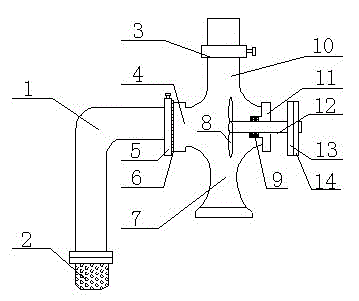
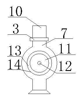
[0014] Such as figure 1 and figure 2 As shown, a pump includes a pump body 7, a pump cover 11, an impeller 7 and a pump shaft 12, the pump body 7 is connected to the pump cover 11, the impeller 7 is connected to the pump shaft 12, and the pump body 7 is A water outlet 10 and a water inlet 4 are provided, the water outlet 10 is provided with a regulating valve 3, which can control the water flow, and the water inlet 4 is provided with a check valve 5, which can prevent the water flow from reversing. The valve 5 is connected with a water inlet pipe 1, the water inlet pipe 1 is provided with a sealing gasket 6, and the bottom is connected with a filter pipe 2, and the pump cover 11 is provided with a sealing ring 9, which can prevent impurities in ...


PUM


Abstract

The invention discloses a pump, and relates to the field of mechanical equipment. The pump comprises a pump body, a pump cover, an impeller and a pump shaft, wherein the pump body is connected with the pump cover; the impeller is connected with the pump shaft; a water outlet and a water inlet are formed in the pump body; an adjusting valve is arranged on the water outlet; a stop valve is arranged on the water inlet, and is connected with a water inlet pipe; a sealing washer is arranged on the water inlet pipe, and a filter screen pipe is connected to the bottom; a sealing ring is arranged on the pump cover; the pump shaft is connected with a belt wheel; and the diameter of the belt wheel is 10-20 cm. The pump has the advantages of capabilities of controlling the water outlet flow, preventing water currents from flowing back, preventing water leakage during work, and preventing impurities in flowing water from entering into the pump and causing the blockage phenomenon.

Description

technical field [0001] The invention relates to the field of mechanical equipment, in particular to a pump. Background technique [0002] The pump is a kind of fluid machinery, that is, a mechanical device that uses fluid as the working medium and energy carrier. It requires a huge amount and different types in industrial and agricultural production. There are many types of pumps on the market, such as The document whose application number is 201220076522.6 discloses a pump, which includes a volute-shaped pump body, an inlet pipe and an outlet pipe arranged on the pump body communicated with the pump body, a motor fixed on the pump body, placed in the pump body and connected to the pump body. The impeller on the output shaft of the motor, at least two outlet pipes with the same water output are evenly distributed on the side wall of the pump body, and each outlet pipe starts from the side wall of the pump body along the tangential direction of the side wall of the pump body ...

Claims


Application Information

Patent Timeline
Patent Type & Authority Applications(China)
IPC IPC(8): F04D1/00F04D15/00F04D29/08F04D29/70F04D29/22
CPCF04D1/00F04D13/02F04D15/0022F04D29/086F04D29/2205F04D29/708
Inventor 张丹嫣
Owner 张丹嫣
Learn More