
Automatic cleaning device for engine cylinder cover

An engine cylinder head, automatic cleaning technology, applied in the direction of cleaning methods, cleaning methods and utensils using gas flow, cleaning methods using liquids, etc., can solve the problem of low drying efficiency, insufficient cleaning targeting, poor cleaning efficiency and effect, etc problem, to achieve the effect of good cleaning, good cleaning effect and good drying effect

Inactive Publication Date: 2015-06-10
CHONGQING HONGYI MACHINERY
View PDF9 Cites 23 Cited by
  • Summary
  • Abstract
  • Description
  • Claims
  • Application Information

AI Technical Summary

Problems solved by technology

However, this kind of cleaning equipment still has the defects of insufficient cleaning pertinence, poor cleaning efficiency and effect
Moreover, in these prior art, the cylinder head is dried by wind blowing or auxiliary electric heating after cleaning, the drying efficiency is low, and the energy consumption is relatively large.
[0005] With the advancement of modern technology, the structure of automobile cylinder heads is becoming more and more complex, with more and more surface holes and irregular shapes. Therefore, it is difficult to ensure good cleaning efficiency and effect and drying by using existing cleaning and drying technologies. Effect

Method used


Image

  • Automatic cleaning device for engine cylinder cover
  • Automatic cleaning device for engine cylinder cover

Examples


Embodiment Construction

[0030] The present invention will be further described in detail below in conjunction with the accompanying drawings.

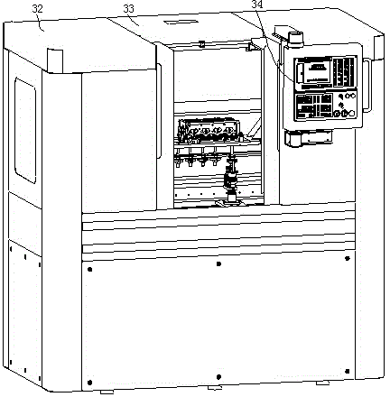
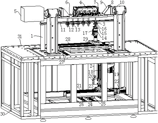
[0031] During specific implementation: if Figure 1-2 Shown, a kind of engine cylinder head automatic cleaning device, comprises frame 1, the engine cylinder head fixing device that is arranged on frame 1 upper end and cleaning mechanism, and cleaning mechanism includes cleaning pipeline 2 and the nozzle 3 that is installed on cleaning pipeline 2 upper ends, The engine cylinder head fixing device is located above the nozzle 3, wherein the cleaning pipeline 2 is a hard pipe and is vertically arranged below the engine cylinder head fixing device, and the lower end of the cleaning pipeline 2 is installed on the frame 1 through a three-dimensional moving device The cleaning pipe 2 can drive the nozzle 3 to move in three-dimensional space. The engine cylinder head fixing device includes a mounting frame for fixing the engine cylinder head 4. The two ends of the mo...


PUM


Abstract

The invention discloses an automatic cleaning device for an engine cylinder cover. The automatic cleaning device comprises a frame, an engine cylinder cover fixing device and a cleaning mechanism, and the engine cylinder cover fixing device and the cleaning mechanism are arranged at the upper end of the frame. The cleaning mechanism comprises a cleaning pipeline and a nozzle mounted on the cleaning pipeline, and the engine cylinder cover fixing device is positioned above the nozzle. The automatic cleaning device is characterized in that the cleaning pipeline is hard and vertically arranged below the engine cylinder cover fixing device, and the lower end of the cleaning pipeline is mounted on the frame through a three-dimensional moving device to enable the cleaning pipeline to drive the nozzle to realize three-dimensional spatial movement; the engine cylinder cover fixing device comprises a mounting frame used for fixing the engine cylinder cover, rotating shafts are outwardly arranged at two ends of the mounting frame respectively and rotatably mounted at the upper end of the frame through bearings, and the rotating shafts are in transmission connection with a rotary servo motor. The automatic cleaning device for the engine cylinder cover is as effective as manual cleaning and has the advantages high cleaning pertinence, effectiveness in cleaning, high cleaning efficiency, excellent drying effects, high drying efficiency, energy saving, consumption reduction and the like.

Description

technical field [0001] The invention relates to an engine cylinder head production and processing technology, in particular to an engine cylinder head automatic cleaning device. Background technique [0002] The engine cylinder head is a component located at the top of the engine in the engine compartment. It creates a closed space for the valves and camshafts and provides holes for installation, while providing passages for lubricating oil. In the production process of the engine cylinder head, after the processing is completed, it needs to go through a cleaning step to remove various metal chips and oil stains attached to it, so as to facilitate subsequent assembly. [0003] Existing automatic cleaning devices for engine cylinder heads are generally cleaned by spraying, and then dried by airflow (or electric heating assisted drying). For example, my country's patent application number 201220601248.X discloses a cleaning device for an automobile engine cylinder head. Its s...

Claims


Application Information

Patent Timeline
Patent Type & Authority Applications(China)
IPC IPC(8): B08B3/02B08B13/00
CPCB08B3/022B08B5/023B08B13/00
Inventor 姜国宾刘继红
Owner CHONGQING HONGYI MACHINERY
Learn More