
Novel tower plate-structure rectifying tower for maleic anhydride refining

The technology of rectifying tower and tray is applied in the field of rectifying tower, which can solve the problems of low production capacity, large steam consumption, decreased acid feeding capacity, etc., so as to achieve the effects of improving the refining capacity of equipment, saving steam consumption and increasing production profits.

Inactive Publication Date: 2015-06-10
TIANJIN BOHUA ZHONGHE CHEM
View PDF0 Cites 5 Cited by
  • Summary
  • Abstract
  • Description
  • Claims
  • Application Information

AI Technical Summary

Problems solved by technology

Among them, there are several valve holes on the floating valve tray, and each valve hole is equipped with a valve plate that can float up and down. The valve plate itself is connected with several valve legs. °, to limit the maximum height of the valve plate rise and prevent the valve plate from being blown away by the gas. The advantages of the valve tray are simple structure and low cost, but the gas flux is low and the production capacity is weak. At the same time, the refining process In the process, the float valve is easily stuck by by-products such as tar, resulting in a decrease in the acid delivery capacity and an increase in the pressure difference in the tower.
The sieve tray tower is composed of air holes on the plate and a cap covering it. The cap is most commonly used in a cylindrical shape. steam
Since the original rectification towers all use valve trays, the production capacity is low, so it needs to be modified, the tray structure should be reasonably selected, and the tower height should be designed according to the tray efficiency to achieve the goal of increasing production capacity and reducing energy consumption

Method used


Image

  • Novel tower plate-structure rectifying tower for maleic anhydride refining
  • Novel tower plate-structure rectifying tower for maleic anhydride refining
  • Novel tower plate-structure rectifying tower for maleic anhydride refining

Examples


Embodiment Construction

[0015] The specific implementation manners of the present invention will be briefly described below in conjunction with the accompanying drawings.

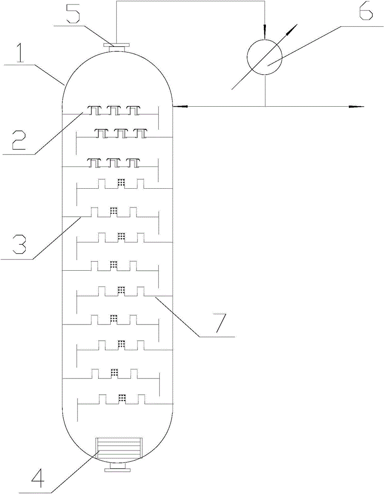
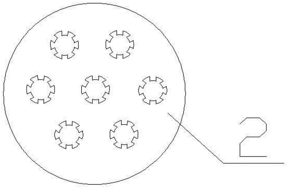
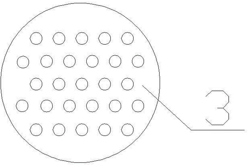
[0016] Such as Figure 1-5 As shown, a rectification tower with a novel tray structure for the purification of maleic anhydride includes a tower body 1, a valve tray group and a sieve tray group, and is characterized in that: the bottom of the tower body 1 is provided with a tower Kettle heater 4, the top of the tower body 1 is provided with a tower top outlet 5, and the tower top outlet 5 is fixedly connected with the condenser 6 through pipelines, and the valve tray group and the sieve tray group are arranged on the tower body 1 Between the inner walls on both sides, it is vertically arranged and fixedly connected with the inner wall of the tower body 1, and the valve tray group is arranged above the sieve tray group, and the valve tray group is composed of several valve tower trays 2 , the sieve tray group is composed of sever...


PUM


Abstract

The invention provides a novel tower plate-structure rectifying tower for maleic anhydride refining. The novel tower plate-structure rectifying tower for maleic anhydride refining comprises a tower body, a float valve tower plate unit and a sieve tower plate unit, the bottom of the tower body is provided with a tower bottom heater, the top of the tower body is provided with a tower top outlet, the tower top outlet is fixedly connected to a condenser by a pipe, the float valve tower plate unit and the sieve tower plate unit are arranged between two side inner walls of the tower body, the float valve tower plate unit comprises several float valve tower plates, the sieve tower plate unit comprises several sieve tower plates, the novel tower plate-structure rectifying tower is used in maleic anhydride rectification purification, the float valve tower plates and eight sieve tower plates are arranged in the tower body. Through reasonable design of the number and positions of the float valve tower plates and the sieve tower plates and current limiting effects of the float valve tower plates, gas flux is partly reduced and a steam use amount is reduced. The novel tower plate-structure rectifying tower effectively utilizes the advantage of a high vertical sieve plate production capacity and improves production efficiency.

Description

technical field [0001] The invention relates to the technical field of rectification equipment, in particular to a rectification tower with a novel tray structure used for the purification of maleic anhydride. Background technique [0002] The refining process of maleic anhydride mainly uses a plate distillation column. Plate distillation column is a kind of equipment used for gas-liquid two-phase staged contact mass transfer. Tray, also known as tray, is the main medium for gas-liquid mass transfer and heat transfer. Under the action of gravity, the liquid flows through each layer of trays from top to bottom in sequence, and is discharged at the bottom of the tower; the gas is driven by pressure difference, and passes through each layer of trays in sequence from bottom to top, and is discharged to the top of the tower. A certain depth of liquid layer is maintained on each tray, and the gas is dispersed into the liquid layer through the tray for interphase contact and mass...

Claims


Application Information

Patent Timeline
Patent Type & Authority Applications(China)
IPC IPC(8): B01D3/16C07D307/60
Inventor 于玉琪顾嘉乐魏新跃刘光磊
Owner TIANJIN BOHUA ZHONGHE CHEM
Learn More