
Method for constructing superconducting magnets for magnetic resonance imaging

A technology of magnetic resonance imaging and superconducting magnets, applied in superconducting magnets/coils, magnetic objects, measuring magnetic variables, etc., can solve the problems of magnet uniformity and other indicators, design results deviate from the optimal solution, etc., to avoid taking The effect of adjusting the error

Inactive Publication Date: 2017-07-18
INST OF HIGH ENERGY PHYSICS CHINESE ACADEMY OF SCI
View PDF4 Cites 3 Cited by
  • Summary
  • Abstract
  • Description
  • Claims
  • Application Information

AI Technical Summary

Problems solved by technology

[0017] The object of the present invention is to provide a method for constructing a superconducting magnet for magnetic resonance imaging, which is used to solve the existing method for superconducting magnets for magnetic resonance imaging. When actually winding the magnet, it is necessary to consider the cross-sectional size of the superconducting wire. The coil size is discretized, and the position and radius are rounded. After rounding and discretization, the uniformity of the magnet and other indicators usually decrease significantly, which makes the design result deviate from the optimal solution.

Method used


Image

  • Method for constructing superconducting magnets for magnetic resonance imaging
  • Method for constructing superconducting magnets for magnetic resonance imaging
  • Method for constructing superconducting magnets for magnetic resonance imaging

Examples


Embodiment Construction

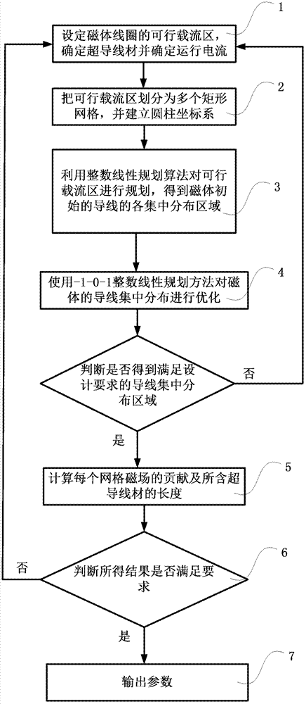
[0027] figure 1 Shown is a schematic diagram of an embodiment of the method for constructing a superconducting magnet for magnetic resonance imaging of the present invention, as figure 1 Shown:

[0028] Step 1. Estimate the maximum range of the feasible current-carrying area of ​​the magnet coil, including the minimum inner radius and maximum outer radius of the feasible current-carrying area. According to the magnetic field design requirements, space constraints and the maximum magnetic induction intensity of the feasible current-carrying area, determine the superconducting wire And determine the operating current Iop;

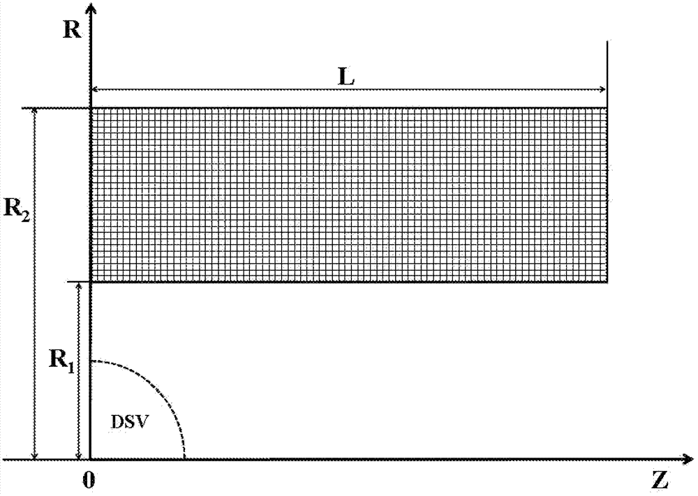
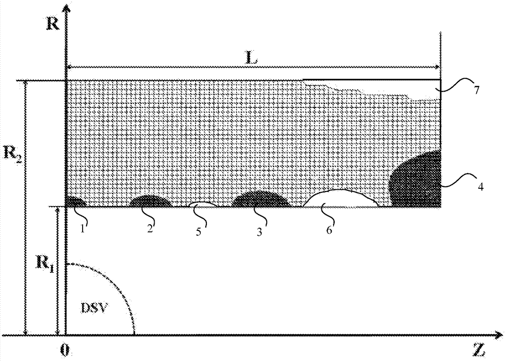
[0029] Step 2, with the center of the magnet as the origin, establish a cylindrical coordinate system (r, z, α), where r is the radial distance, the z-axis is the height, α is the azimuth angle, and the magnet axis is the z-axis direction; according to the Select the size of the superconducting wire, and divide the feasible current-carrying region into mult...


PUM


Abstract

A method for constructing a superconducting magnet for magnetic resonance imaging, including: determining a superconducting wire material, a running current and a feasible current-carrying zone; dividing the feasible current-carrying zone into a plurality of rectangular grids, rounding off rectangular grids at the boundary, adjusting the boundary of the feasible current-carrying zone, and acquiring the number of the rectangular grids in the feasible current-carrying zone; with the centre of a magnet as an origin, establishing a coordinate system to obtain the space coordinate of the centre of each rectangular grid; with the minimal wire consumption as an optimization goal, and the field intensity of the centre, the magnetic field uniformity and the stray field as constraint conditions, programming the feasible current-carrying zone with a linear integer programming algorithm to obtain each concentrated distribution area of an initial wire of the magnet; according to the degree of influence of each concentrated distribution area on the magnetic field uniformity, and according to the degree of influence on the magnetic field uniformity in descending order, with the minimal wire consumption as the optimization goal, and the field intensity of the centre, the magnetic field uniformity and the stray field as the constraint conditions, rectangularizing each concentrated distribution area with the linear integer programming algorithm; and acquiring the parameters of a superconducting magnet coil.

Description

technical field [0001] The invention belongs to the field of applied superconducting technology, in particular to a method for constructing a magnetic resonance imaging (Magnetic Resonance Imaging, MRI for short) superconducting magnet. Background technique [0002] Magnetic resonance imaging (MRI) is a high-tech imaging technology that utilizes the NMR properties of the magnetic nuclei (mainly hydrogen nuclei) of organisms in a magnetic field. Magnetic resonance imaging (MRI) equipment is mainly composed of a main magnet, a scanning bed, a gradient coil, a radio frequency coil, a spectrometer system, a control cabinet, a man-machine dialogue console, a computer, and an image processor. [0003] The main magnet is the main component of the MRI equipment, used to generate a uniform static magnetic field, which determines the image quality and work efficiency of the MRI equipment. At the same time, the main magnet is also the part with the largest manufacturing cost and the h...

Claims


Application Information

Patent Timeline
IPC IPC(8): H01F6/00H01F41/02G01R33/3815
CPCG01R33/3815H01F41/048
Inventor 张国庆朱自安赵玲侯治龙杨欢周谨马文彬王克祥
Owner INST OF HIGH ENERGY PHYSICS CHINESE ACADEMY OF SCI
Learn More