
Analog filter

An analog filter and output waveform technology, applied in the direction of transverse filter, filter, impedance network, etc., can solve the problems of complex composition, output waveform skew, rounding error, etc., to reduce the number and avoid rounding error. , a simple effect

Inactive Publication Date: 2003-02-12
酒井康江
View PDF0 Cites 0 Cited by
  • Summary
  • Abstract
  • Description
  • Claims
  • Application Information

AI Technical Summary

Problems solved by technology

However, because the sine function tends to 0 at ±∞, rounding errors occur in the calculation, and the skew problem of the output waveform still occurs
In addition, there are issues whose composition becomes extremely complex

Method used


Image

  • Analog filter
  • Analog filter
  • Analog filter

Examples


Embodiment 1

[0051] The analog filter of Embodiment 1 performs a predetermined multiple of oversampling and moving average operation or overlapping operation (hereinafter referred to as convolution operation) on the binary signal (1-bit signal) modulated by ΔΣ , an analog signal with smoothness and less skew can be obtained.

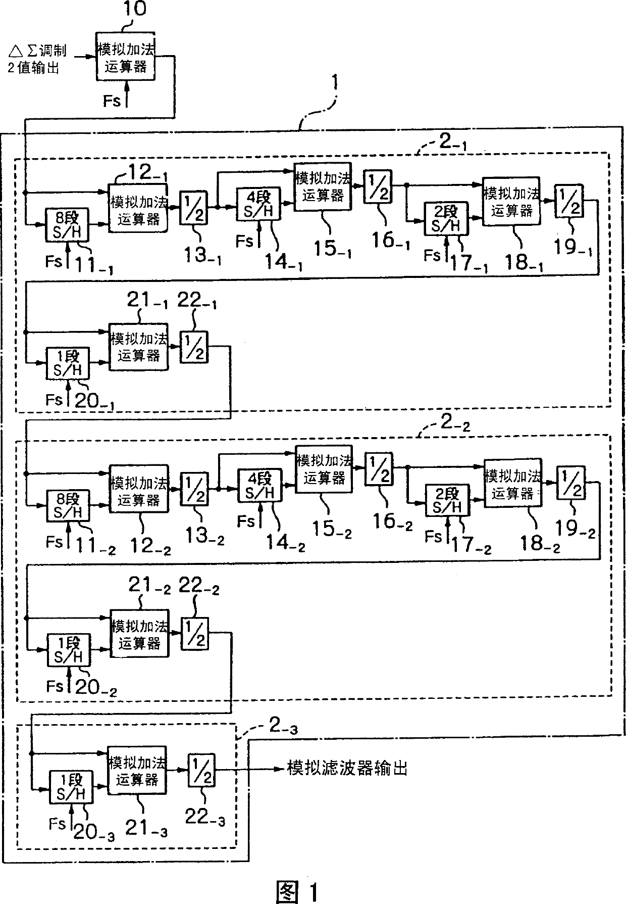
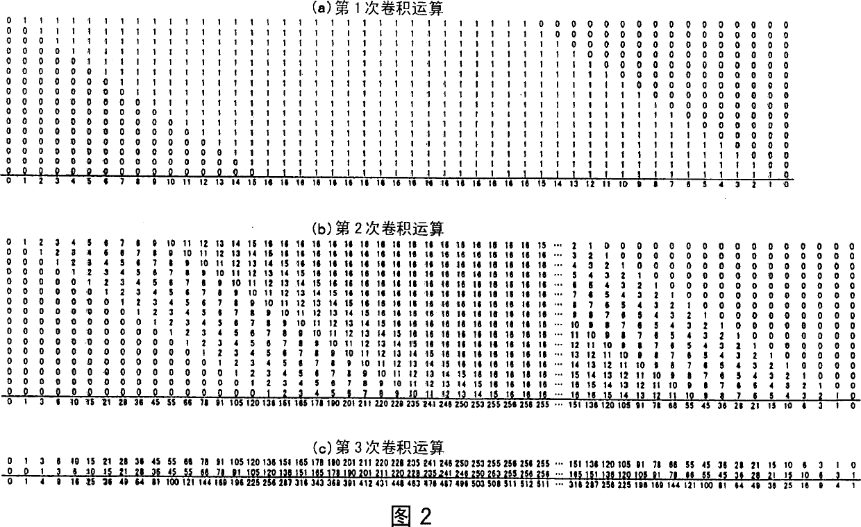
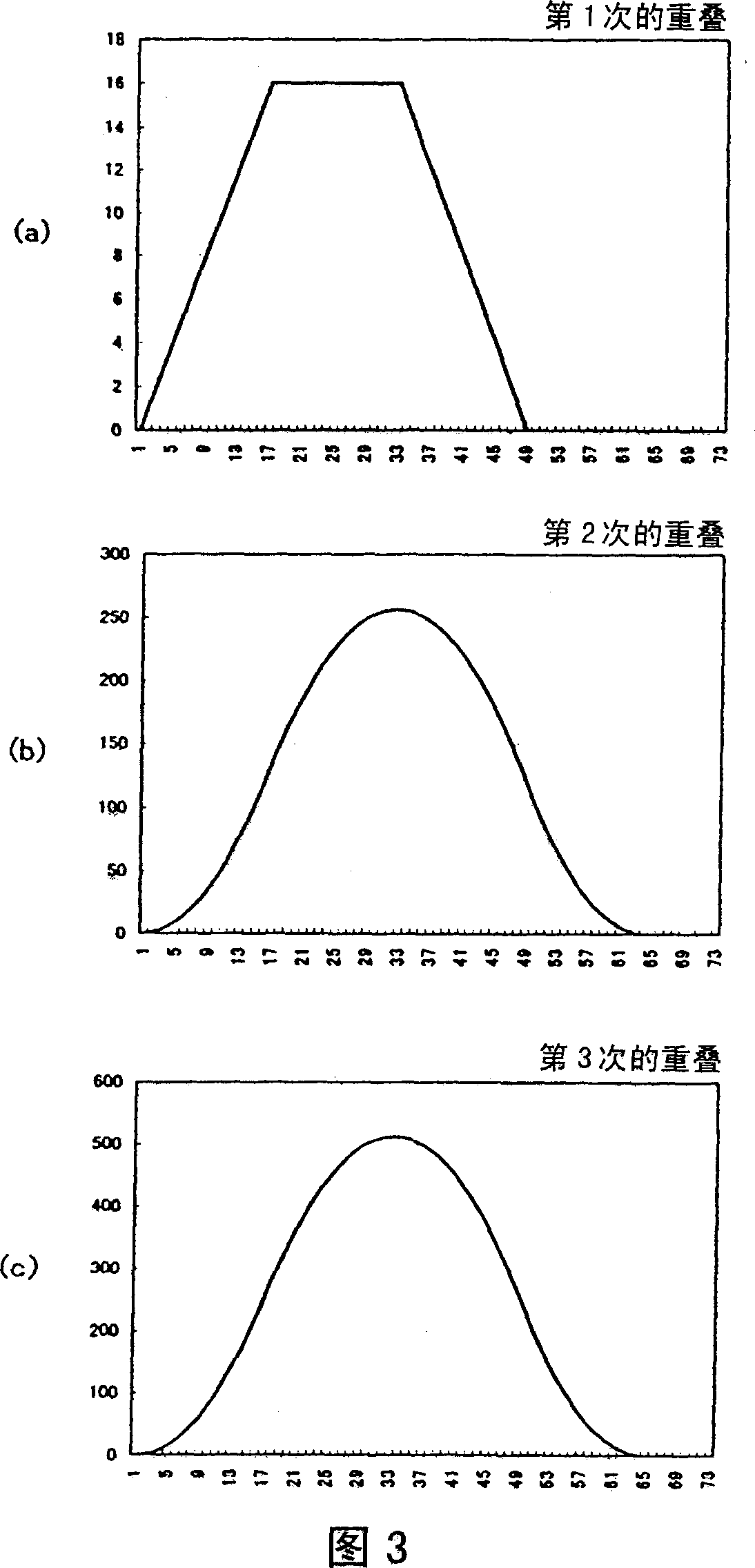
[0052] FIG. 1 is a block diagram showing an example of the configuration of an analog filter of this embodiment. 2 and 3 are diagrams illustrating the principle of operation of the analog filter of this embodiment. First, the operation principle will be described using Fig. 2 and Fig. 3 .

[0053] Figures 2 and 3 show that the unit time determined by the sampling frequency f is set to T (=1 / f), and the time width 2nT (set to n=16 in Figure 2) and the single amplitude of 1 The process of converting a rectangular wave to an analog signal through filter processing.

[0054] FIG. 2( a ) shows an example of processing of 2n times oversampling and the first convolution ...

Embodiment 2

[0080] Embodiment 2 of the present invention will be described below.

[0081] The analog filter of Embodiment 2 weights the ΔΣ-modulated binary signal (1-bit signal) with a digital basic waveform corresponding to a predetermined sampling function described below, and for the The output signal is subjected to the convolution operation described in Embodiment 1 to obtain a smooth analog signal.

[0082] Fig. 7 is a block diagram showing an example of the configuration of an analog filter of this embodiment. Fig. 8 is a time flow chart showing the operation time. In addition, FIG. 9 is a diagram showing a digital basic waveform, and FIG. 10 is a diagram showing a waveform obtained by subjecting the digital basic waveform to analog filter processing. First, the operation principle will be described using Fig. 9 and Fig. 10 .

[0083] The digital basic waveform shown in FIG. 9 is the basis of the sampling function used when performing the analog filter processing of this embodi...


PUM


Abstract

An analog filter comprising a first arithmetic operation section 2-1 consisting of a plurality of sets of processing circuit being cascade connected, each processing circuit having an S / H circuit of plural stages for holding a DELTA SIGMA -modulated signal and an analog adder for adding the input and output signals of the S / H circuit, in which the number of stages of the S / H circuits 11-1, 14-1, 17-1 and 20-1 decreases toward the end of cascade connection, and a second arithmetic operation section 2-2 configured in the same way, which are cascade connected. By using such an analog filter, over-sampling and convolution of a DELTA SIGMA -modulated signal are conducted so that the envelope of the filter output may be a quadratic curve of finite carrier that converges to zero at finite sampling points to prevent phase distortion of an LPF and a discretization error due to a conventional function. Compared with a conventional circuit for over-sampling and convolution, the number of stages of the S / H circuits and the number of adders are small.

Description

technical field [0001] The present invention relates to analog filters, eg filters suitable for smoothing delta sigma modulated signals. Background technique [0002] ΔΣ modulation is to convert the analog signal into a digital signal by symbolizing the change amount of the current data for the data of each sample point that has been sampled in the time of each predetermined number of sampling frequencies. its digital approach. That is, in ΔΣ modulation, the amplitude component of a similar signal is represented by only two numerical values ​​(1 bit). [0003] When this ΔΣ modulation is used, for example, to code an audio signal, in the ΔΣ modulation method, compared with the PCM method adopted by the CD (Compact Disk), which is widely used at present, not only can the overall configuration be simplified, It also has the advantage of improving the resilience of the vertical digital signal back to the original analog signal by controlling the distribution of quantization no...

Claims


Application Information

Patent Timeline
Patent Type & Authority Applications(China)
IPC IPC(8): H03H11/04H03H15/02H03H17/02H03M3/02H04B14/06
CPCH03H11/04H03H17/02H03H17/026
Inventor 小柳裕喜生
Owner 酒井康江
Learn More