
Harmonic current detection and filtration method and device of active power filter

A power filter and harmonic current technology, applied in active power filtering, harmonic reduction devices, AC networks to reduce harmonics/ripples, etc., can solve low resolution, small A/D sampling signals, all Problems such as a small proportion, to improve the detection accuracy, avoid rounding errors, and improve the compensation effect

Inactive Publication Date: 2012-11-21
ENERTECH SUZHOU ENERGY TECH CO LTD
View PDF0 Cites 2 Cited by
  • Summary
  • Abstract
  • Description
  • Claims
  • Application Information

AI Technical Summary

Problems solved by technology

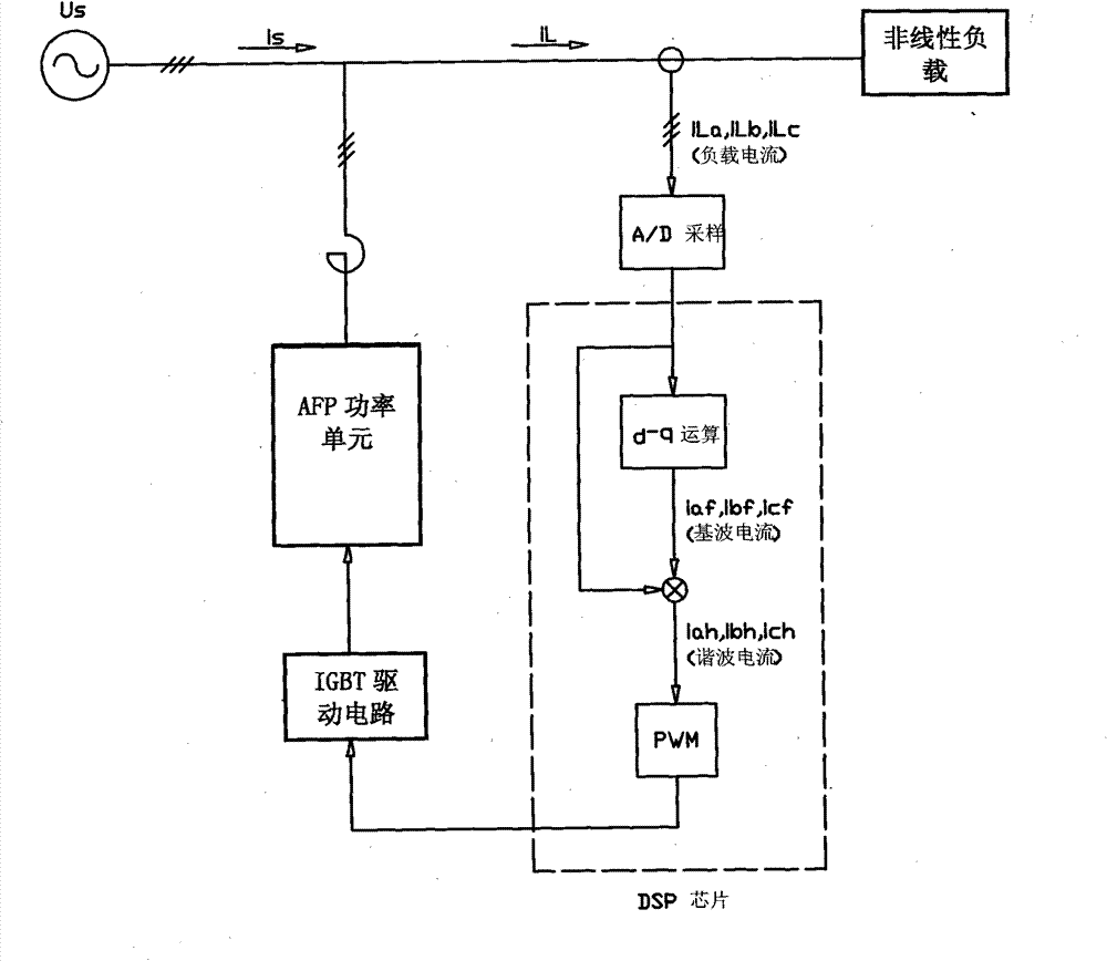
figure 1 It is a block diagram of the existing active power filter load current detection and processing principle. Since the load current is designed according to the maximum load, the detected load current may be small due to the change of the load during the actual commissioning process, which will inevitably cause A / D sampling signal is small
Although the harmonic current generated by some loads is relatively large, it still accounts for a small proportion compared with the fundamental current of the load. The resolution of the wave current signal will be relatively low, so the sampled harmonic current will be too small compared with the sensor range, causing distortion and thus affecting the compensation effect of the active power filter
At present, signal amplification is used to solve this problem, but the input range of the A / D converter is only about 5V, so the signal amplification factor cannot be increased too much

Method used


Image

  • Harmonic current detection and filtration method and device of active power filter
  • Harmonic current detection and filtration method and device of active power filter
  • Harmonic current detection and filtration method and device of active power filter

Examples


Embodiment

[0025] Embodiment: A harmonic current detection and filtering method of an active power filter, comprising:

[0026] Step 1-1, the current detection sensor detects the three-phase load current in the grid, and the three-phase load current includes the fundamental component current and the harmonic component current generated by the load;

[0027] Step 1-2, dividing the three-phase load current in the grid into two branches, which are respectively the three-phase load current of the first branch and the three-phase load current of the second branch;

[0028] Step 1-3, removing the harmonic component current of the first branch three-phase load current through a filter, thereby obtaining the first branch fundamental wave component current, the step 1-3 further includes the following steps: Step 2-1, combining the three The three-phase load current of the first branch in the phase A-B-C coordinate system is transformed into the two-phase load current in the two-phase coordinate s...


PUM


Abstract

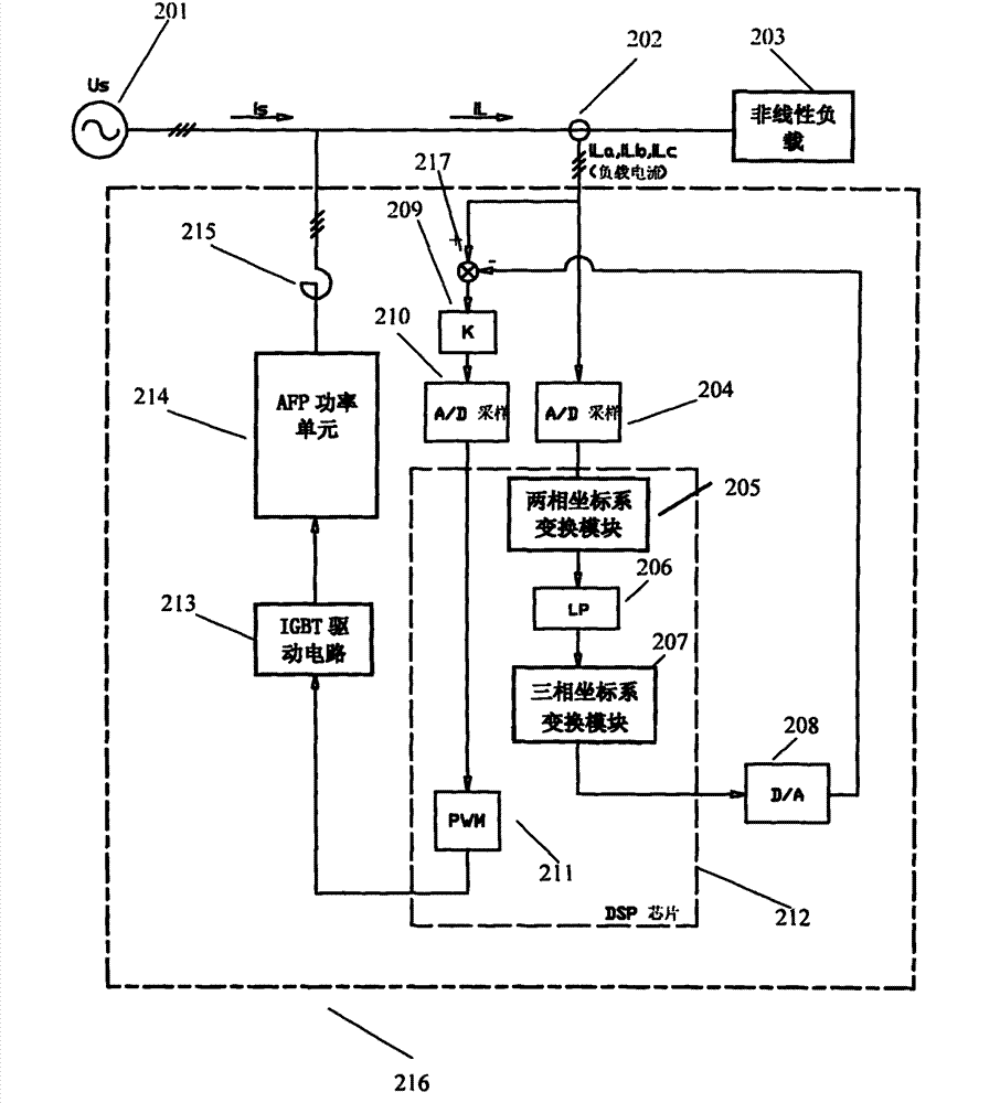
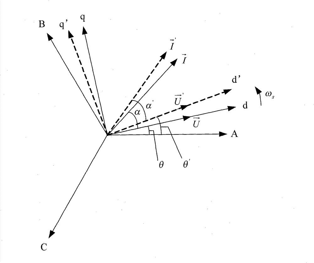
The invention relates to a harmonic current detection and filtration device of an active power filter, which comprises an output reactor, a power unit, a drive circuit, a two-phase coordinate system conversion module, a low pass filter module, a three-phase coordinate system conversion module and a subtracter. The two-phase coordinate system conversion module is used for converting a three-phase load current into a two-phase load current in a two-phase coordinate system, namely a d-q coordinate system. The two-phase coordinate system is in synchronous rotation with a voltage vector in a circuit, wherein the rotation angular frequency is omega s. The low pass filter module is used for filtering the harmonic component currents of the components d and q in the two-phase load current output by the two-phase coordinate system conversion module, so as to obtain the fundamental component current. The three-phase coordinate system conversion module is used for converting the fundamental component current processed by the low pass filter module into a fundamental component current of a three-phase load current in a three-phase coordinate system. The subtracter is used for subtracting the fundamental component current output by the three-phase coordinate system conversion module from the three-phase load current, so as to obtain a harmonic signal current. The method and the device have the advantages of accurate detection and can filter the harmonic current in the active power filter.

Description

technical field [0001] The invention relates to a harmonic current detection filter device of an active power filter, which belongs to the field of power quality control. Background technique [0002] In recent years, the widespread use of power electronic devices and nonlinear loads has caused a large amount of harmonic current and reactive current to be injected into the grid, which seriously threatens the safe operation and normal use of the grid and electrical equipment. Filtering and compensation of harmonic reactive power has been People pay more and more attention to it. [0003] There are a number of disadvantages to using passive filtering devices to solve reactive and harmonic problems. For example, passive filters are mostly designed for harmonics of specific frequencies, and can only filter out specific sub-harmonics, which may cause resonance with the power grid; and are very sensitive to grid impedance and frequency changes; large volume, large loss, etc. Wai...

Claims


Application Information

Patent Timeline
Patent Type & Authority Patents(China)
IPC IPC(8): G01R19/25H02J3/01H02J3/18
CPCY02E40/40Y02E40/22Y02E40/20
Inventor 汤玉明吴祥兴
Owner ENERTECH SUZHOU ENERGY TECH CO LTD
Learn More