Display device and liquid crystal display device
A liquid crystal display device and a display device technology, which are applied in identification devices, lighting devices, lighting and heating equipment, etc., and can solve problems such as image brightness reduction and uneven brightness
- Summary
- Abstract
- Description
- Claims
- Application Information
AI Technical Summary
Problems solved by technology
Method used
Image


Examples
Embodiment approach 1
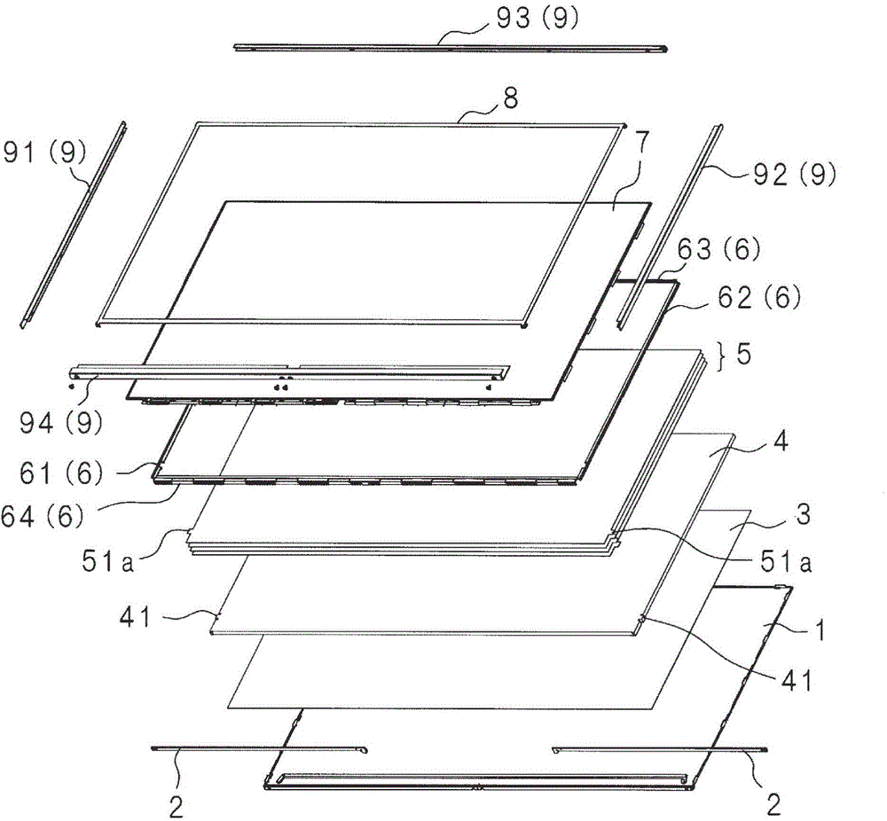
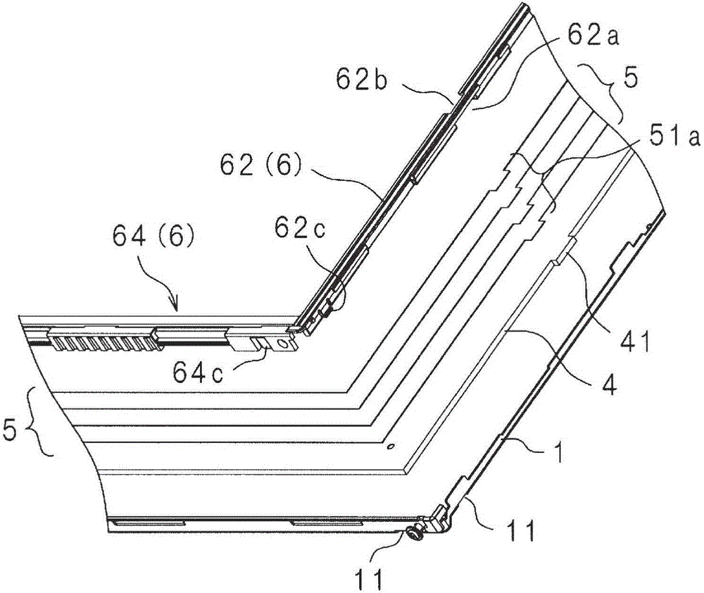
[0164] Hereinafter, the display device according to the embodiment of the present invention will be described by taking a television receiver as an example. figure 1 It is a perspective view of the appearance of a television receiver. figure 2 It is an exploded perspective view of the main parts of the TV receiver. The television receiver includes a backlight base 1 (holding body), an LED (Light Emitting Diode) substrate 2, a reflective sheet 3, a light guide plate 4, an optical sheet 5, an optical member bracket 6 (positioning member), and liquid crystal The panel 7 (display panel), the panel cover 8, the outer frame 9, the tuner substrate 10, and the power supply substrate 11.
[0165] In the following description, the side of the television receiver where the liquid crystal panel 7 is provided is referred to as the front side or simply the front. The side opposite to the front side is called the back side or simply the back. The left side facing the liquid crystal panel 7 is...
Embodiment approach 2
[0197] Hereinafter, the present invention will be specifically described based on the drawings showing embodiments of the present invention. Picture 10 It is an exploded perspective view showing the structure of the liquid crystal display device of this embodiment. Picture 11 It is a partially enlarged cross-sectional view showing the structure of the liquid crystal display device of this embodiment. In the figure, 201 is a liquid crystal panel. The liquid crystal panel 201 has a substantially rectangular plate shape, and is a display that performs image display by controlling the transmittance of light irradiated from the back for each pixel. A plurality of optical sheets 202, a light guide plate 203, and a reflection plate 204 are stacked on the back side of the liquid crystal panel 201. The plurality of optical sheets 202 have different optical characteristics, and are optical members that perform light diffusion and the like. Each optical sheet 202 has a substantially re...
Deformed example 1
[0217] The contact surface 272a of the light shielding member 207 has a comb shape, but it may have another shape as shown in the following modification examples. Figure 14 It is a schematic diagram which shows the modification of the contact surface 272a of the light shielding member 207. Figure 14 The abutting surface 272a of the light shielding member 207 shown in A adopts a grid shape. The plurality of grooves 272b are substantially square, respectively, and are arranged in the longitudinal direction and the lateral direction. In addition, Figure 14 The light-shielding member 207 shown in B is formed by arranging substantially circular grooves 272b in a row, and the contact surface 272a is a shape formed by removing a plurality of substantially circular shapes from a substantially rectangular shape. In addition, the contact surface 272a of the light shielding member 207 is not limited to the shape shown in the figure, and various shapes can be further adopted.
PUM
 Abstract
Description
Claims
Application Information
 - R&D
- Intellectual Property
- Life Sciences
- Materials
- Tech Scout
- Unparalleled Data Quality
- Higher Quality Content
- 60% Fewer Hallucinations
Browse by: Latest US Patents, China's latest patents, Technical Efficacy Thesaurus, Application Domain, Technology Topic, Popular Technical Reports.
© 2025 PatSnap. All rights reserved.Legal|Privacy policy|Modern Slavery Act Transparency Statement|Sitemap|About US| Contact US: help@patsnap.com