Charge control device

A charging control and charger technology, applied in circuit devices, battery circuit devices, measuring devices, etc., can solve the problems of misjudgment of battery abnormality when the battery is fully charged, shorten the charging time, and easily control the charging current. Effect of preventing increase of charging current

Active Publication Date: 2015-06-03
MAKITA CORP
View PDF4 Cites 4 Cited by
  • Summary
  • Abstract
  • Description
  • Claims
  • Application Information

AI Technical Summary

Problems solved by technology

[0012] Therefore, when the battery temperature drops during charging, as when the battery temperature rises, the charging of the battery is stopped, the battery cannot be charged to a fully charged state, and an abnormality of the battery is misjudged, causing misunderstanding to the user. such problem

Method used


Image

  • Charge control device
  • Charge control device
  • Charge control device

Examples


Embodiment Construction

[0050] The following is attached Figure 1 Embodiments of the present invention will be described first.

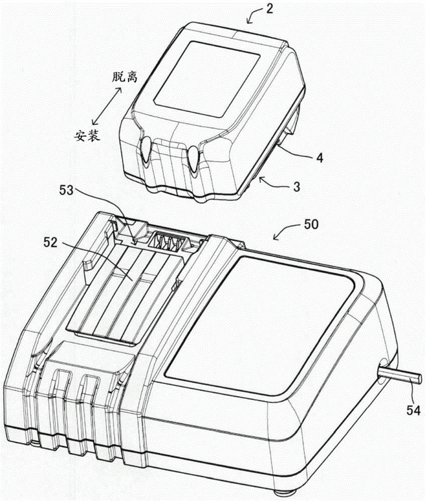
[0051] Such as figure 1 As shown, the charging system of this embodiment is detachably mounted on various rechargeable electric equipment such as rechargeable electric tools, rechargeable vacuum cleaners, rechargeable lawn mowers, etc. The battery pack 2 for power supply and the charger 50 for charging the battery pack 2 are constituted.

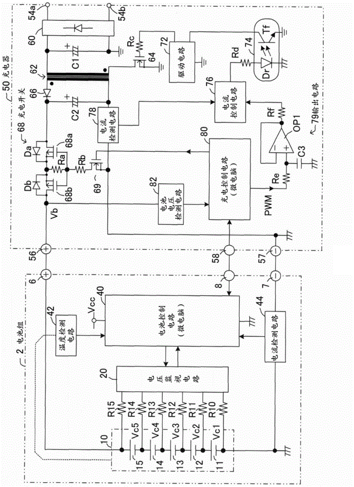
[0052] The charger 50 receives power supply from an external power source (generally commercial power supply: AC voltage) via a power line 54, thereby generating a charging voltage (DC voltage) for battery charging, and charging the battery 10 in the battery pack 2 (refer to image 3 ) for power supply.

[0053] On the upper surface of the charger 50 is formed a mounting portion 52 for mounting (that is, placing) the battery pack 2 . The mounting portion 52 is formed to correspond to the shape of the mounting portion 3 on the rear ...


PUM


Abstract

A charge control device includes a voltage detector (82) that detects a voltage of a battery (2), a temperature detector (42) that detects a temperature of the battery (2), a voltage setting unit (80, 40) that sets at least one of a charge completion voltage and an abnormality determination voltage to a high temperature time voltage that is lower than a normal voltage when the battery temperature detected by the temperature detector (42) is or is above a high temperature determination threshold set in advance, and a charging current limiting unit (80, 40) that reduces a charging current a charger (50) supplies to the battery (2) when the battery temperature is in a temperature range between a set temperature that is lower by a predetermined temperature than the high temperature determination threshold and the high temperature determination threshold and the battery voltage detected by the voltage detector (82) is in a voltage range between the normal voltage and the high temperature time voltage, during charging of the battery (2) by the charger (50).

Description

technical field [0001] The present invention relates to a charge control device that switches between a charging completion voltage and an abnormality determination voltage according to the temperature of a battery. Background technique [0002] In the past, in lithium-ion batteries, such as Figure 9 As shown in the illustration, the temperature range during charging is classified into three regions: low temperature region (T1~T2), normal temperature region (T2~T3), and high temperature region (T3~T4), and the battery voltage is specified for each region. The maximum value Vmax (for example, refer to Patent Document 1). [0003] Therefore, the charging control device for controlling the charging of such a battery sets the charging completion voltage as the target voltage during charging for each of the above-mentioned temperature ranges so that the battery voltage during charging does not exceed the maximum value Vmax specified above. , Abnormal judgment voltage for batter...

Claims


Application Information

Patent Timeline
IPC IPC(8): H02J7/00
CPCH01M10/443H01M10/48H01M10/486H01M10/0525H02J7/0031Y02E60/10H02J7/00309H02J7/007182H02J7/007194G01R31/382H02J7/00
Inventor 梅村卓也小早川忠彦上杉纮生花井宽
Owner MAKITA CORP
Why Eureka
Try Eureka