
Solid-state imaging device

A solid-state imaging device and pixel technology, applied in electric solid-state devices, radiation control devices, image communication, etc.

Inactive Publication Date: 2015-06-03
KK TOSHIBA
View PDF0 Cites 2 Cited by
  • Summary
  • Abstract
  • Description
  • Claims
  • Application Information

AI Technical Summary

Problems solved by technology

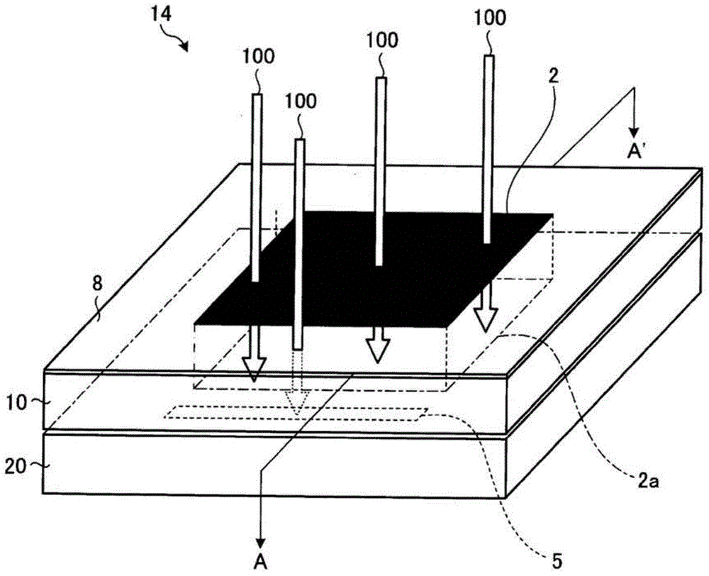
[0003] However, in this solid-state imaging device, when the memory is irradiated with light transmitted from the pixel array, the information stored in the memory may be rewritten by the light irradiation.

Method used


Image

  • Solid-state imaging device
  • Solid-state imaging device
  • Solid-state imaging device

Examples


Embodiment Construction

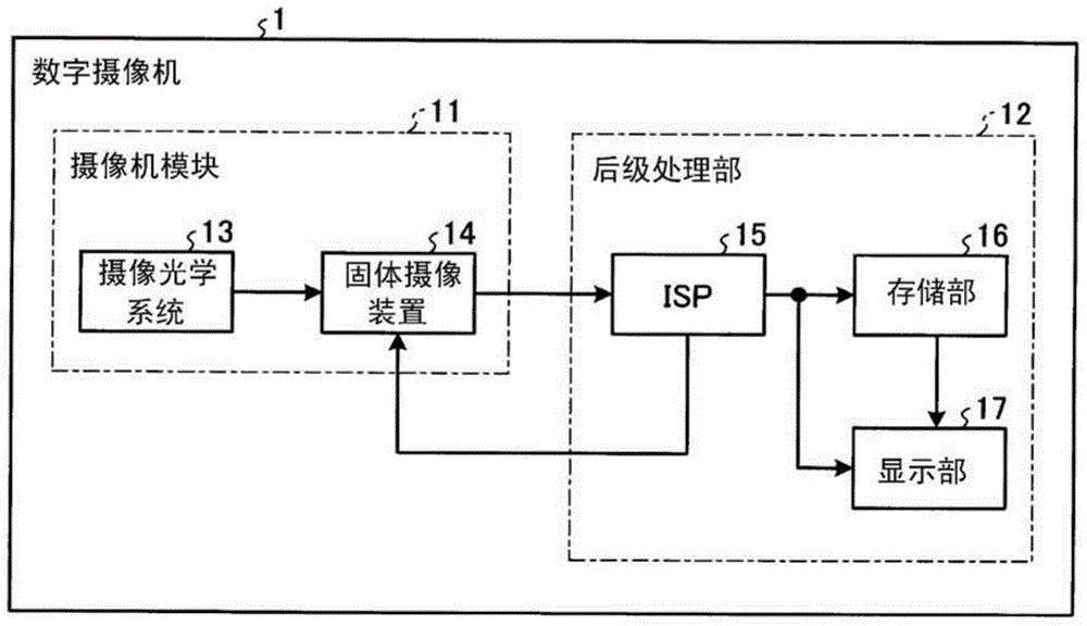
[0041] Hereinafter, the solid-state imaging device according to the embodiment will be described in detail with reference to the drawings. In addition, this invention is not limited by this embodiment. figure 1 It is a block diagram showing a schematic configuration of a digital camera (digital camera) 1 including a solid-state imaging device 14 according to the embodiment. Such as figure 1 As shown, the digital camera 1 includes a camera module 11 and a post-processing unit 12 .

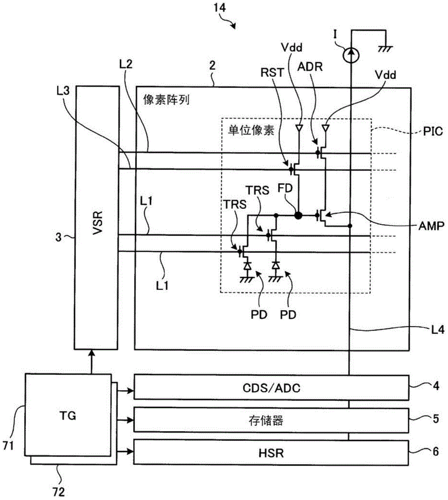
[0042] A camera module (camera module) 11 includes an imaging optical system 13 and a solid-state imaging device 14 . The imaging optical system 13 takes in light from a subject to form a subject image. The solid-state imaging device 14 captures a subject image formed by the imaging optical system 13 , and outputs a pixel signal corresponding to each pixel of the image obtained by the imaging to the subsequent processing unit 12 . The camera module 11 is applicable to, for example, electronic eq...


PUM


Abstract

A solid-state imaging device includes a first chip and a second chip. The first chip includes a pixel array in which a plurality of photodiodes corresponding to each pixel of a captured image is disposed in a two-dimensional array shape. Each photodiode generates a pixel signal corresponding to a signal charge generated by the photoelectric conversion of the photodiode. The first chip is stacked on the second chip that includes a memory storing the pixel signals generated from the first chip, where the memory is located outside a projection region formed by projecting the pixel array and in a thickness direction of the first chip.

Description

technical field [0001] Embodiments of the present invention relate to a solid-state imaging device. Background technique [0002] Conventionally, there is a solid-state imaging device in which a first chip having a pixel array in which a plurality of photoelectric conversion elements corresponding to a captured image are arranged in a two-dimensional array and a second chip having a storage circuit such as a memory are bonded and laminated. up, thereby reducing the dedicated area of ​​the device. [0003] However, in this solid-state imaging device, when the memory is irradiated with light transmitted from the pixel array, the information stored in the memory may be rewritten by the irradiation of the light. Contents of the invention [0004] The problem to be solved by the invention [0005] An object of one embodiment of the present invention is to provide a solid-state imaging device capable of preventing information stored in a memory from being rewritten by light tr...

Claims


Application Information

Patent Timeline
Patent Type & Authority Applications(China)
IPC IPC(8): H01L27/146H04N25/00
CPCH01L27/14634H04N25/778H04N25/79H04N25/78H04N25/772H04N25/75
Inventor 田中长孝
Owner KK TOSHIBA
Learn More