
Continuous welding device for laser welder of impeller of water pump

A laser welding machine and water pump impeller technology, applied in the field of fixtures, can solve the problems of high production cost, low work efficiency, low material utilization rate, etc., and achieve the effects of ensuring positioning accuracy, improving production efficiency, and improving cutting speed.

Active Publication Date: 2015-06-03
ANHUI SHUNYU WATER AFFAIRS CO LTD
View PDF5 Cites 2 Cited by
  • Summary
  • Abstract
  • Description
  • Claims
  • Application Information

AI Technical Summary

Problems solved by technology

[0002] At present, manual argon arc welding is mostly used for impeller welding. When welding, first manually spot weld the blade and one impeller cover plate, and then weld the blade and another impeller cover plate. This welding method is difficult to guarantee the position accuracy of the blade, and the work efficiency is not good. High; there is also a method of welding twice, using a mold to position the blade during the first welding, so that the blade and an impeller cover are welded, and no mold is used for the second welding; in addition, the blade section is made into a "U" shape, or Make the entire blade into a radial corrugated plate, which can improve the structural strength of the impeller, but the material utilization rate is low and the production cost is high

Method used


Image

  • Continuous welding device for laser welder of impeller of water pump
  • Continuous welding device for laser welder of impeller of water pump
  • Continuous welding device for laser welder of impeller of water pump

Examples


Embodiment Construction

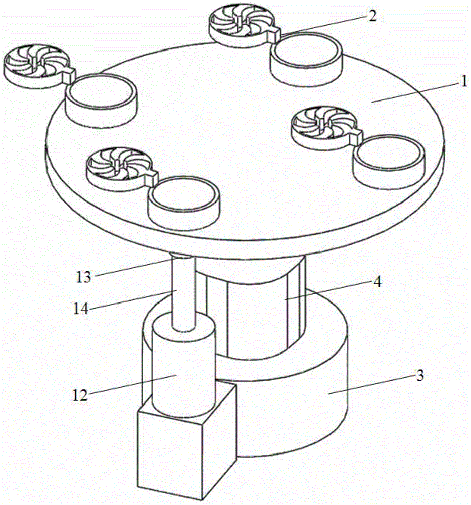
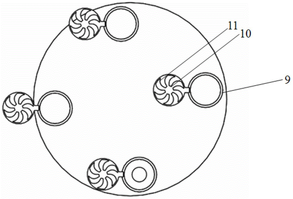
[0016] see Figure 1-3 As shown, a continuous welding device for a water pump impeller laser welding machine includes an automatic rotating disk 1 and an impeller fixing fixture 2 arranged on the automatic rotating disk 1, the bottom of the automatic rotating disk 1 is provided with a base 3, and the A motor 4 is installed in the middle of the base 3, the rotating shaft 5 of the motor 4 is equipped with a driving gear 6, and the driven gear 7 is fixed on the automatic rotating disk 1 by a screw 8, and the driving gear 6 and the driven gear 7 are engaged with each other; the impeller The fixing fixture comprises an impeller base fixing die 9 and a blade fixing bracket 10. The inner diameter of the impeller base fixing die 9 is 0.1 mm larger than the upper limit of the outer diameter of the impeller base. The blade fixing bracket 10 consists of two concentric rings and The impeller fixing bar 11 welded in the middle of the ring is formed;

[0017] Preferably, an ejector is prov...


PUM


Abstract

The invention relates to a continuous welding device for a laser welder of an impeller of a water pump. The continuous welding device for the laser welder of the impeller of the water pump comprises an automatic rotating plate and an impeller fixing clamp, wherein the impeller fixing clamp is arranged on the automatic rotating plate; a base is arranged on the lower portion of the automatic rotating plate; a motor is arranged in the middle of the base; a driving gear is arranged on a rotating shaft of the motor; a driven gear is fixed on the automatic rotating plate through screws; the driving gear and the driven gear are gripped with each other; the impeller fixing clamp comprises an impeller base fixing concave die and a blade fixing support; the blade fixing support consists of two concentric rings and an impeller fixing barrier strip welded to the middles of the rings; an ejector is arranged on the bottom of the automatic rotating plate and comprises a cylinder, a foot switch and an ejection lever; and the ejection lever is arranged on a piston of the cylinder. The blade fixing support is made of peek and is connected to the base through hinges. The continuous welding device for the laser welder of the impeller of the water pump is simple in structure, novel in design, convenient to operate and high in production efficiency, and has an automatic continuous welding function.

Description

Technical field [0001] The present invention involves a kind of tooling fixture, especially a continuous welding device for a water pump leaf wheel laser welding machine. Background technique [0002] At present, the impeller welding mostly uses handmade arc welding. When welding, first hand -welded leaves and a leaf wheel cover, and then welded with blades and another leaf wheel cover.High; there are also two methods of welding. When the first welding is used to locate the blades, the leaves and a leaf wheel cover are welded, and the mold is not used in the second welding.The entire blade is made into a radiation ripple -shaped plate. Although it can improve the strength of the impeller, the material utilization rate is low and the production cost is high. [0003] Some companies have replaced laser welding, and laser welding makes up for the disadvantages of traditional resistance welding welding.The line sealing rate of the front and rear cover of the leaf wheel and the blades...

Claims


Application Information

Patent Timeline
IPC IPC(8): B23K26/21B23K26/70
CPCB23K26/20
Inventor 邓帮武陈前宏方皖蜀
Owner ANHUI SHUNYU WATER AFFAIRS CO LTD
Learn More