A vacuum welding device and its installation and use method

A vacuum welding and pedestal technology, applied in welding equipment, metal processing equipment, manufacturing tools, etc., can solve the problems of shape and position tolerance, unable to complete multiple key parts of the main body at the same time, to improve the yield, smooth the path, avoid uncontrollable effects

Active Publication Date: 2021-07-20
BEIJING INST OF RADIO METROLOGY & MEASUREMENT
View PDF6 Cites 0 Cited by
  • Summary
  • Abstract
  • Description
  • Claims
  • Application Information

AI Technical Summary

Problems solved by technology

[0003] This application proposes a vacuum welding device and its installation and use method, which aims to solve the problem in the prior art that the vacuum sealing of multiple key parts of the main body cannot be completed at the same time, resulting in uncontrollable shape and position tolerances caused by multiple processes

Method used


Image

  • A vacuum welding device and its installation and use method
  • A vacuum welding device and its installation and use method
  • A vacuum welding device and its installation and use method

Examples


Embodiment 1

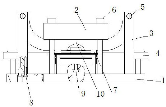
[0044] A vacuum welding device, see figure 1 , including a bottom base 1, a transverse top plate 2, a longitudinal side wall adjustment column 3, a longitudinal magnetic shield adjustment screw 4 and a transverse adjustment screw 5;

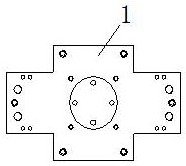
[0045] please see figure 2 and image 3 , the left side and the right side of the bottom base 1 are respectively connected with side wall adjustment columns 3, the bottom base 1 is provided with a table for placing the main body 10 of the U-shaped structure, and the table is located between the side wall adjustment columns 3 The arc-shaped convex surface between;

[0046] please see Figure 4 , Figure 5 , the bottom base 1 is provided with a top platen 2 for clamping and fixing the main body 10 with the table top, and the first platen for fixing the top platen 2, the main body 10 and the bottom base 1 passes between the top platen 2 and the bottom base 1 The fixing part 6 is connected and fixed;

[0047] please see Figure 6 and Figure...

Embodiment 2

[0059] A vacuum welding device, similar to Embodiment 1, the difference is that at least four first fixing holes evenly distributed in a square are arranged on the main body 10, the top platen 2 and the bottom base 1 respectively, the main body 10, The top pressing plate 2 and the bottom base 1 are connected and fixed through the first fixing member 6 arranged in the first fixing hole.

[0060] It may further be provided that at least four second fixing holes evenly distributed into a square are arranged on the table and the main body 10, the second fixing holes are screw holes, and the outer wall of the second fixing member 7 is provided with The external thread matched with the second fixing hole, the main body 10 and the bottom base 1 are connected through the second fixing member 7 arranged in the second fixing hole.

[0061] It can be further improved that column holes are respectively provided on the left and right sides of the upper surface of the bottom base 1, and the...


PUM


Abstract

The application discloses a vacuum welding device and its installation and use method. There are side wall adjustment columns on the left and right sides of the bottom base of the vacuum welding device. There is a top pressure plate above the base, and the top pressure plate and the bottom base are connected and fixed by the first fixing piece; the upper part of the side wall adjustment column is located in front of the upper part of the longitudinal part of the U-shaped structure of the main body, and the upper part of the side wall adjustment column has front and rear respectively. The adjustment screw in the direction; the bottom base outside the side wall adjustment column is connected with a magnetic shield adjustment screw; it ensures that the vacuum sealing of multiple key parts of the main body is completed at the same time, and avoids uncontrollable shape and position tolerances caused by multiple processes; applicable The assembly is welded in a high-temperature vacuum environment to ensure the shape and position tolerances of its key positions, and to ensure that the path of cesium atoms is smooth and does not deviate; the main body can be welded once and can be used for a long time, and the yield of cavity components can be improved.

Description

technical field [0001] The present application relates to the technical field of main body welding and manufacturing, and relates to a vacuum welding device and an installation and use method. Background technique [0002] At present, the main body is a key component of cesium clock physics. How to assemble and weld the various structures of the main body is a key issue in its application process. For this reason, a vacuum welding device is needed so that the main body can be smoothly placed in a high-temperature vacuum environment. The assembly is welded down to ensure the shape and position tolerances of its key positions, thereby ensuring that the path of the cesium atoms is smooth and does not deviate. The Chinese utility model patent document whose notification number is CN204248234U discloses a welding device for cesium release agent for electric vacuum, including a material tube box, a material tube feeding device, two casing boxes, two sets of casing feeding devices,...

Claims


Application Information

Patent Timeline
Patent Type & Authority Patents(China)
IPC IPC(8): B23K28/00
CPCB23K28/003
Inventor 刘朝华王一非高连山
Owner BEIJING INST OF RADIO METROLOGY & MEASUREMENT
Why Eureka
Try Eureka