
Coating device and coating method

A technology of coating device and coating liquid, which is applied in the direction of surface coating liquid device, coating, pretreatment surface, etc., which can solve the problem of increased resistance at the seam in the nozzle, decreased film thickness accuracy, and ejection action. Delay and other problems, to achieve the effect of reducing resistance and high productivity

Active Publication Date: 2015-05-27
TORAY ENG CO LTD
View PDF7 Cites 4 Cited by
  • Summary
  • Abstract
  • Description
  • Claims
  • Application Information

AI Technical Summary

Problems solved by technology

[0004] When using such a coating device to start coating a relatively high-viscosity coating liquid on a substrate, due to the resistance of the resin piping from the pump to the nozzle and the slits in the nozzle, the coating will start to slow down when the pump starts to operate. The flow of the liquid and the ejection of the coating liquid from the slit are delayed, and the delay causes the thickness of the coating film to decrease at the start of coating, which affects the coating quality.
[0005] In addition, if the supply speed of the coating liquid from the pump is increased in order to apply a relatively high-viscosity coating liquid at high speed, the resistance at the slit in the nozzle will increase, and the internal pressure will increase.
Due to this increase in internal pressure, the elongated linear slit is deformed into an elongated drum shape, and the thickness of the film formed by the coating liquid sprayed from the central portion of the slit in the longitudinal direction (width direction) becomes smaller. The thickness of the film is thicker than that of the edge, and the film thickness is different in the width direction, and the accuracy of the film thickness will be greatly reduced.
In addition, in order to form a coating film of the same thickness using a high-viscosity coating liquid and a low-viscosity coating liquid, there is also the following principle problem: if the high-viscosity coating liquid is not coated with a lower-viscosity coating liquid, If the cloth speed (moving speed of the nozzle) is low, such a coating film cannot be formed

Method used


Image

  • Coating device and coating method
  • Coating device and coating method
  • Coating device and coating method

Examples


Embodiment Construction

[0032] Hereinafter, embodiments of the present invention will be described based on the drawings.

[0033] (Structure of coating device)

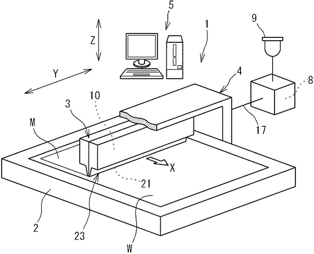
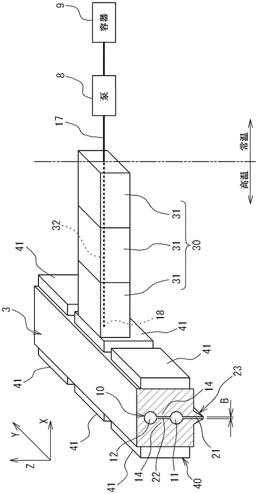
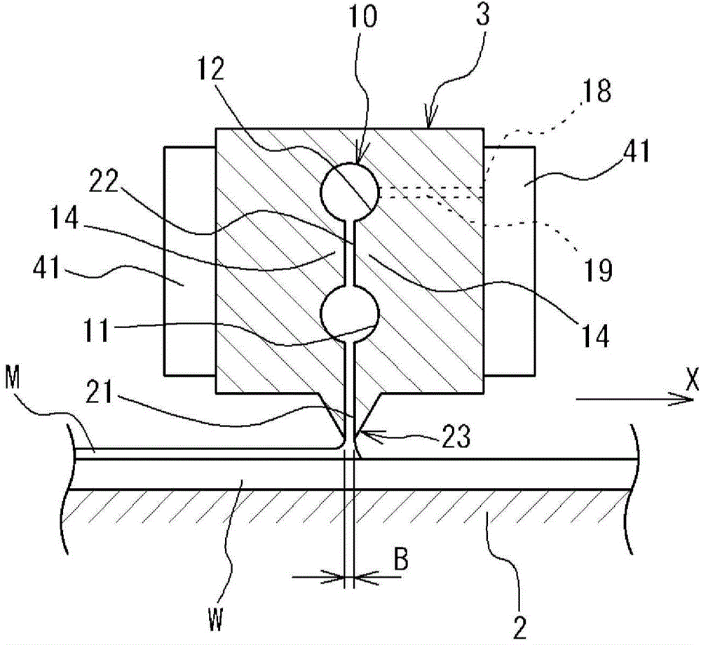
[0034] figure 1 It is a schematic diagram showing an embodiment of the coating device 1 of the present invention. The coating device 1 has: a stage 2, which can place a substrate W such as glass; a nozzle 3, in which a slit 21 is formed; and a driving device 4, which allows the nozzle 3 to freely perform relative to the stage 2 Horizontal movement (X-direction movement) and vertical movement (Z-direction movement) of the substrate W. In addition, the coating apparatus 1 further has a liquid feeding mechanism as a liquid supply unit, and the liquid feeding mechanism is composed of a container 9 storing the coating liquid, a pump 8 for supplying the coating liquid in the container 9 to the nozzle 3, and the like. Between the pump 8 and the nozzle 3, a resin-made pipe (pipe) 17 constituting a flow path of the coating liquid is provided.

[0035] I...


PUM


Abstract

The present invention forms a coating film on a substrate with good precision and at high speed even when coating a coating solution of relatively high viscosity on the substrate. Specifically, the coating device (1) is provided with a tank (9) for storing the coating solution and a nozzle (3) in which a slit (21) for discharging the coating solution supplied from the tank (9) is formed. The coating solution is coated on the substrate by discharging the coating solution from the slit (21). The coating device (1) is provided with a temperature-raising unit (30) for raising the temperature of the coating solution supplied from the tank (9) and a temperature-homogenizing unit (40) for homogenizing the temperature of the coating solution, the temperature of which has been raised by the temperature-raising unit, prior to discharging the coating solution from the slit (21).

Description

Technical field [0001] The present invention relates to a coating device and a coating method for applying a coating liquid to a substrate by ejecting a coating liquid from a slit formed in a nozzle. Background technique [0002] As an apparatus for applying a coating liquid to a substrate such as a glass substrate and a film, the following coating apparatus is known (for example, refer to Patent Document 1), which has a nozzle formed with a slit for ejecting the coating liquid . The coating device includes a container for storing the coating liquid, and a pump for supplying the coating liquid in the container to the slit of the nozzle. [0003] The slit is formed long along the width direction of the substrate. For example, the coating liquid can be sprayed from the slit while moving the nozzle horizontally with respect to the substrate placed on the stage to form a coating on the surface of the substrate. Liquid thin film (coating film). [0004] When using such a coating device...

Claims


Application Information

Patent Timeline
IPC IPC(8): B05C5/02B05C11/10B05D1/26B05D3/00
CPCB05C5/001B05C5/0208B05C5/0254B05C11/1007B05C11/1015B05C11/1042B05D1/26
Inventor 林田健儿北村义之川竹洋大霜征彦村尾幸一
Owner TORAY ENG CO LTD
Learn More