
Externally heated heat loading device capable of rapidly heating

An external heating, thermal loading technology, applied in electric heating devices, ohmic resistance heating, electrical components, etc., can solve the problems of low temperature rise rate, small maximum heating temperature and temperature rise rate, poor production continuity, etc. Thermal efficiency, the effect of improving heat utilization

Active Publication Date: 2015-05-27
GENERAL ENG RES INST CHINA ACAD OF ENG PHYSICS
View PDF5 Cites 10 Cited by
  • Summary
  • Abstract
  • Description
  • Claims
  • Application Information

AI Technical Summary

Problems solved by technology

[0003] Existing heat loading devices mostly use electric heating, limited by the resistance wire material and heat conduction and convection as the main heat conduction methods, the medium is required to transmit heat energy, the loss of energy is large, and the heat conduction needs to be in contact with the object to be heated, the maximum The heating temperature and temperature rise rate are generally small. Due to the slow thermal loading rate and safety factors, it is often suitable for long-term thermal loading with low power. Heating the heated object to a higher temperature in a short period of time cannot reach the high temperature working area above 600°C, and there are disadvantages such as large energy consumption, low temperature rise rate, low efficiency, and poor production continuity.

Method used


Image

  • Externally heated heat loading device capable of rapidly heating
  • Externally heated heat loading device capable of rapidly heating
  • Externally heated heat loading device capable of rapidly heating

Examples


Embodiment Construction

[0018] The present invention will be further described below in conjunction with accompanying drawing:

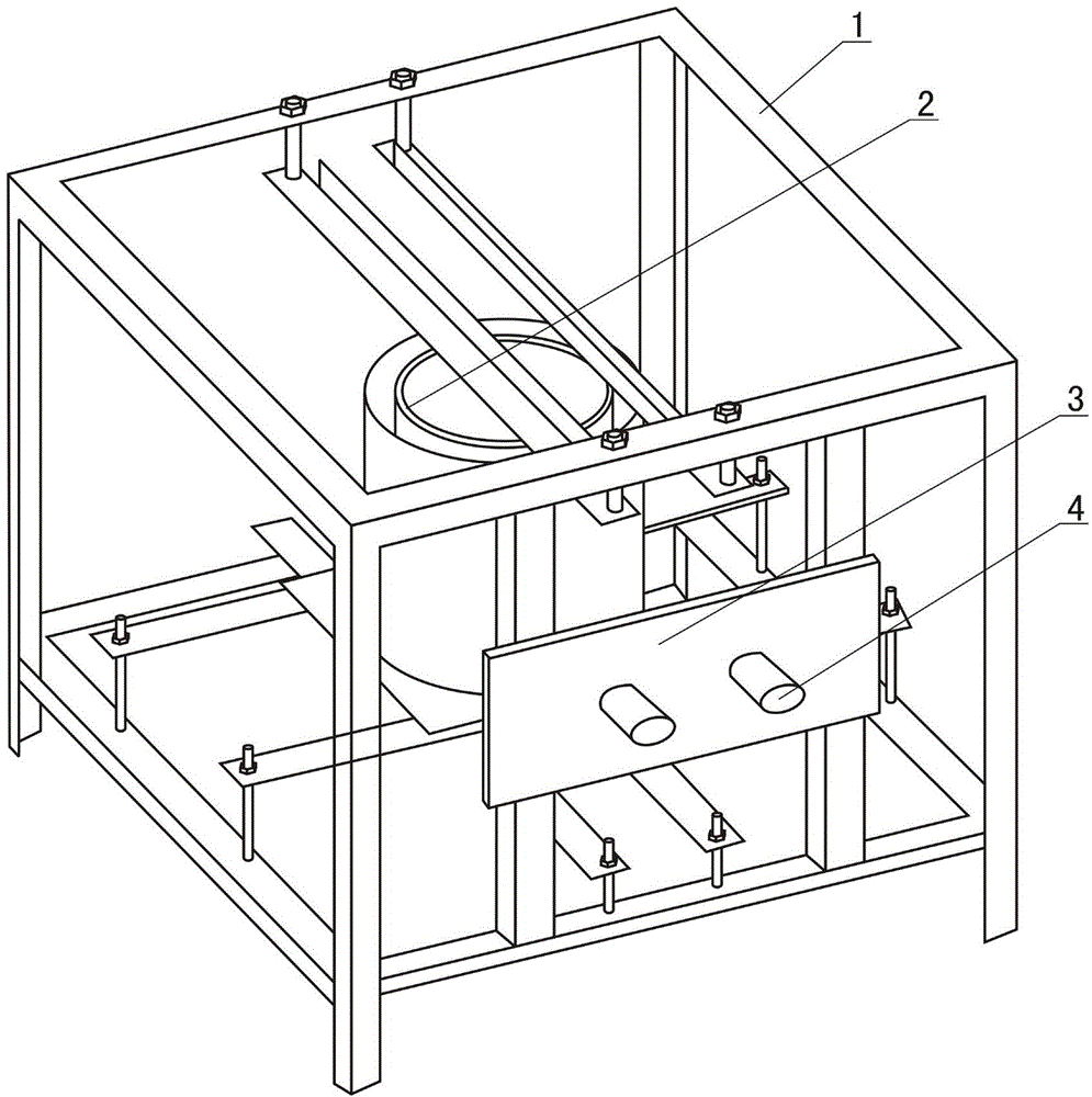
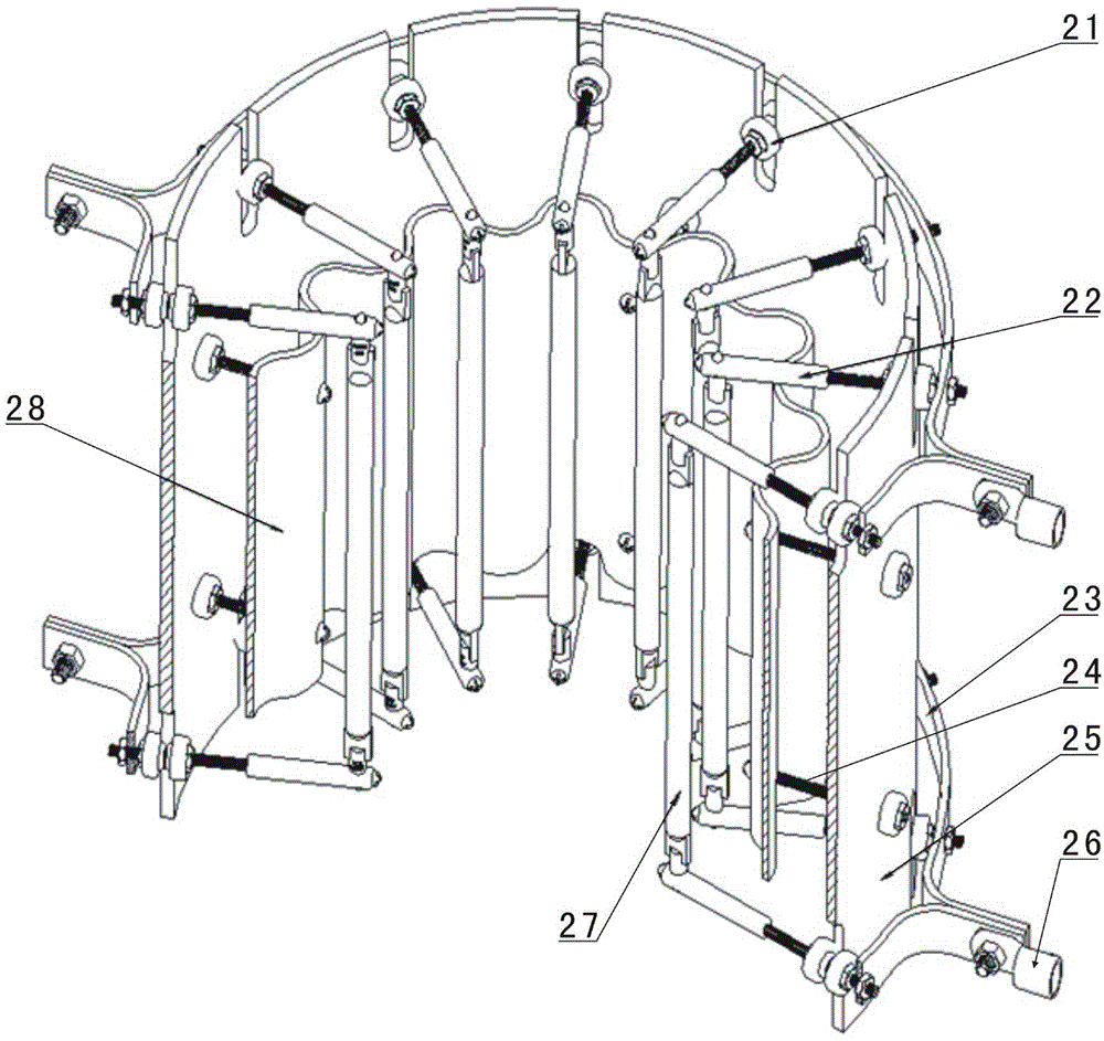
[0019] Such as figure 1 As shown, the external heating type thermal loading device 2 of the present invention is installed on the frame 1 during application, and the frame 1 is also equipped with a terminal block 3 and a terminal post 4 located on the terminal block 3. The power connection terminal of the external heating type heat loading device 2 is correspondingly connected with the terminal post 4, so that the external heating type heat loading device 2 can be powered on. illustrate, figure 1 The external heating type heat loading device 2 is only a schematic diagram, and figure 2 The specific structure of the device looks different, but they are all the same device.

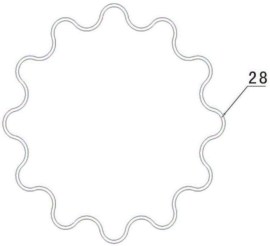
[0020] Such as figure 2 and image 3 As shown, the rapid heating-up external heat-loading device of the present invention includes a quartz lamp tube 27, a lamp tube clamp 22, an aluminum cylinder ...


PUM


Abstract

The invention discloses an externally heated heat loading device capable of rapidly heating. According to the externally heated heat loading device capable of rapidly heating, a reflector is formed by connecting and closing a plurality of reflector units together, and the radial section of each reflector unit is circular-arc-shaped; a plurality of vertical lamp tubes are mounted in the vertical inner cavity of the reflector; the plurality of lamp tubes correspond to the plurality of reflector units one to one; the positions of the lamp tubes are arranged within the corresponding regions of cambered grooves formed in the inner sides of the corresponding reflector units; the plurality of lamp tubes are evenly distributed in a virtual and encircled manner to form a space for holding materials to be heated; the reflector and all the lamp tubes are all arranged in a cylinder which is vertical and open in upper and lower ends; the two ends of each lamp tube are electrically connected with two conducting rings by use of lamp tube clamps; the lamp tube clamps all penetrate through the cylinder. The externally heated heat loading device capable of rapidly heating is provided with the reflector for inwards reflecting light emitted by the lamp tubes to the outside, and therefore, the heat utilization rate of the lamp tube is increased; meanwhile, due to the adopted radiant heat conduction manner, the device has the heat loading capability with high temperature rise rate and high heating temperature and is capable of meeting the requirements of the high temperature rise rate and high temperature loading.

Description

technical field [0001] The invention relates to a heat loading device, in particular to an external heating type heat loading device with rapid temperature rise. Background technique [0002] Thermal loading devices are often used in materials, chemical engineering, metallurgy and other engineering fields. With the continuous development of new materials and new processes, higher requirements are put forward for the heating power, temperature rise time and energy consumption cost of thermal loading. For example, the heating temperature required for the preparation of rubber asphalt, which can significantly improve the mechanical properties and performance of asphalt pavements, and the test temperature for the temperature resistance of airgel materials have reached above 600°C; With a wide range of working fluids, on the premise of ensuring sufficient resolution, rapid temperature rise can realize rapid analysis of its composition and physical properties. Therefore, the perf...

Claims


Application Information

Patent Timeline
Patent Type & Authority Applications(China)
IPC IPC(8): H05B3/00
Inventor 季锡林胡宇鹏王小龙王军汤紫峰
Owner GENERAL ENG RES INST CHINA ACAD OF ENG PHYSICS
Learn More