
Power supply system of air energy water heater and control method of power supply system

A technology of air energy water heater and power supply system, which is applied in the direction of electrical program control, program control, and general control system, etc., and can solve problems such as increasing the failure rate of air energy water heaters, high standby power consumption of power modules, and damage to main control board components. Achieve zero power consumption in standby, reduce standby power consumption, and reduce failure rate

Active Publication Date: 2015-05-27
HEFEI MIDEA HEATING & VENTILATING EQUIP
View PDF6 Cites 5 Cited by
  • Summary
  • Abstract
  • Description
  • Claims
  • Application Information

AI Technical Summary

Problems solved by technology

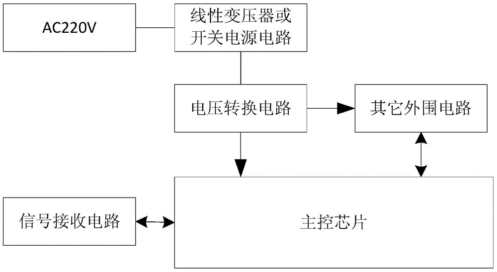
[0004] However, due to the large standby power consumption of the power module, the figure 1 In the power supply mode shown, even if the whole machine is in standby mode or low power consumption mode, the air energy water heater still has a power loss ranging from several hundred milliwatts to several watts. For a single family, although the annual loss is only Several kilowatts to tens of kilowatts, but for a large number of users, the annual loss will be very high
[0005] In addition, due to the uncontrollability of the power grid environment, such as voltage fluctuations, instantaneous surges or lightning strikes, etc., it will cause permanent damage to the main control board components in the air energy water heater that has been in standby mode or low power consumption mode for a long time, increasing The failure rate of air energy water heater

Method used


Image

  • Power supply system of air energy water heater and control method of power supply system
  • Power supply system of air energy water heater and control method of power supply system
  • Power supply system of air energy water heater and control method of power supply system

Examples


Embodiment Construction

[0032] Embodiments of the present invention are described in detail below, examples of which are shown in the drawings, wherein the same or similar reference numerals designate the same or similar elements or elements having the same or similar functions throughout. The embodiments described below by referring to the figures are exemplary only for explaining the present invention and should not be construed as limiting the present invention.

[0033] The following disclosure provides many different embodiments or examples for implementing different structures of the present invention. To simplify the disclosure of the present invention, components and arrangements of specific examples are described below. Of course, they are merely examples and are not intended to limit the invention. Furthermore, the present invention may repeat reference numerals and / or letters in different instances. This repetition is for the purpose of simplicity and clarity and does not in itself indic...


PUM


Abstract

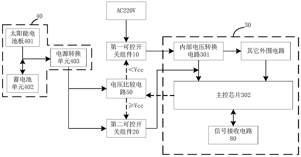
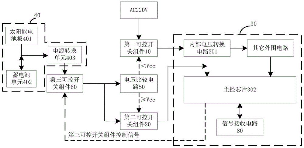
The invention discloses a power supply system of an air energy water heater. The power supply system comprises a first controllable switch assembly, a master control panel control module, a solar cell module, a second controllable switch assembly and a voltage comparison circuit, wherein the master control panel control module comprises an internal voltage conversion circuit and a master control chip and is used for converting the input alternating current to output a first direct-current power supply to the power supply end of the master control chip when the first controllable switch assembly is in closed state; the solar cell module is used for outputting a second direct current power supply; when the air energy water heater is in the standby mode, the voltage comparison circuit controls the second controllable switch assembly to close and control the first controllable switch assembly to disconnect when judging that the voltage of the second direct current power supply is greater than or equal to a reference voltage. The power supply system can be used for supplying power by the solar cell module when the air energy water heater is in the standby mode, so that the standby power consumption of the air energy water heater is reduced and the failure rate of the air energy water heater is reduced at the same time. The invention further discloses a control method of the power supply system of the air energy water heater.

Description

technical field [0001] The invention relates to the technical field of air energy water heaters, in particular to a power supply system of the air energy water heater and a control method of the power supply system of the air energy water heater. Background technique [0002] At present, the commonly used power supply methods for household appliances are as follows: figure 1 As shown, among them, the power module adopts linear transformer or switching power supply. When the home appliance is working normally, the power supply module supplies power to the entire motherboard components in the home appliance, and when the shutdown signal is received or the whole machine is in standby waiting for a preset trigger, the main control chip will enter the standby mode or low power consumption mode At this time, other peripheral circuits such as compressor control, fan control, etc. will be disconnected, and only the main control chip retains some functional applications, such as rec...

Claims


Application Information

Patent Timeline
Patent Type & Authority Applications(China)
IPC IPC(8): G05B19/04
CPCG05B19/0423
Inventor 余根刘仁欢胡志强沈宝生陈照辉
Owner HEFEI MIDEA HEATING & VENTILATING EQUIP
Learn More