
Novel optical fiber gyroscope sensor

A fiber optic gyroscope and sensor technology, applied in the field of sensors, can solve problems such as strong noise and large errors

Inactive Publication Date: 2015-05-27
XIAN DAYU PHOTOELECTRIC TECH
View PDF0 Cites 2 Cited by
  • Summary
  • Abstract
  • Description
  • Claims
  • Application Information

AI Technical Summary

Problems solved by technology

In China, the development of new fiber optic gyro sensors has been relatively rapid in recent years. At present, the known optical gyro sensors use semiconductor lasers to generate light beams, which are composed of optical couplers, polarizers, polarizing films and polarization-maintaining fiber rings, but they are still not available. Avoid the determination of large errors, strong noise, etc.

Method used


Image

  • Novel optical fiber gyroscope sensor

Examples


Embodiment Construction

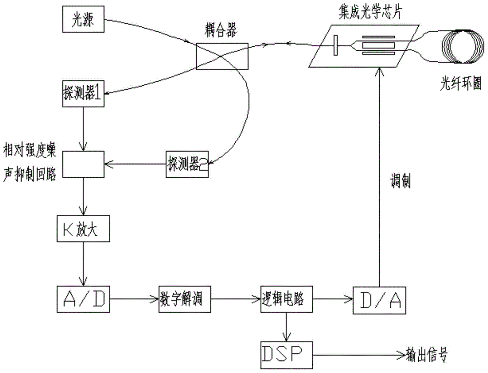
[0011] As shown in Figure 1, the present invention mainly consists of a light source, a coupler, an integrated optical chip, an optical fiber loop, a detector 1, a detector 2, a noise suppression circuit, an amplifier circuit, A / D, digital demodulation, logic circuit, D / A and dsp composition.

[0012] In this example, the optical path is detected by two detectors after passing through the coupler. The two detectors are connected to the noise suppression circuit. Both detectors use photodetectors with high gain, low noise and high sensitivity. The relative noise can be effectively eliminated through the noise suppression circuit. The noise suppression circuit is connected to the A / D through the amplifying circuit, and the signal output by the suppression circuit can be amplified again, and converted into a signal suitable for digital demodulation through analog-to-digital conversion, and then the signal is connected to the logic circuit through digital demodulation. . After t...


PUM


Abstract

The invention relates to a novel optical fiber gyroscope sensor. The sensor mainly comprises a light source, a coupler, an integrated optical chip, an optical fiber loop, a detector 1, a detector 2, a noise suppression loop, an amplifying circuit, an A / D module, a digital demodulator, a logic circuit, a D / A conversion circuit and DSP, wherein strength noise is completely eliminated by using a noise related method by the double detectors, the light source adopts the double detectors after passing through the coupler, the two detectors are connected with the noise suppression loop, and then connected with the logic circuit through a discharging circuit, the A / D module and the digital demodulator; the D / A conversion circuit is connected with the integrated optical chip and the optical fiber loop after being adjusted. Through the adoption of the sensor, the strength noise can be effectively eliminated, and the output precision of the optical fiber gyroscope sensor is improved.

Description

technical field [0001] The invention relates to the field of sensors, in particular to a novel optical fiber gyro sensor. Background technique [0002] Since the 1970s, the development of the gyro sensor has entered a new stage. After the 1980s, the modern new fiber optic gyro sensor has developed very rapidly. Because the new fiber optic gyro sensor has a compact structure and high sensitivity , reliable operation, small size, low cost and other advantages, so the new fiber optic gyro sensor has completely replaced the traditional gyro sensor of the mechanic in many fields. In foreign countries, new fiber optic gyro sensors have been widely used in aerospace, weapon navigation, robot control, oil drilling and radar. In China, the development of new fiber optic gyroscope sensors has been relatively rapid in recent years. At present, it is known that the disclosed optical gyroscope sensors use semiconductor lasers to generate light beams, which are composed of optical couple...

Claims


Application Information

Patent Timeline
IPC IPC(8): G01C19/72
CPCG01C19/72
Inventor 张超胡剑锋
Owner XIAN DAYU PHOTOELECTRIC TECH
Learn More