
Method And System For Improved Dilution Purging

一种车辆系统、发动机的技术,应用在装料系统、运输和包装、发动机的起动等方向,能够解决增加燃烧稳定性问题发动机失火等问题

Active Publication Date: 2015-05-27
FORD GLOBAL TECH LLC
View PDF5 Cites 3 Cited by
  • Summary
  • Abstract
  • Description
  • Claims
  • Application Information

AI Technical Summary

Problems solved by technology

The presence of increased intake air dilution at low loads can increase combustion stability problems and the propensity of the engine to misfire

Method used


Image

  • Method And System For Improved Dilution Purging
  • Method And System For Improved Dilution Purging
  • Method And System For Improved Dilution Purging

Examples


Embodiment Construction

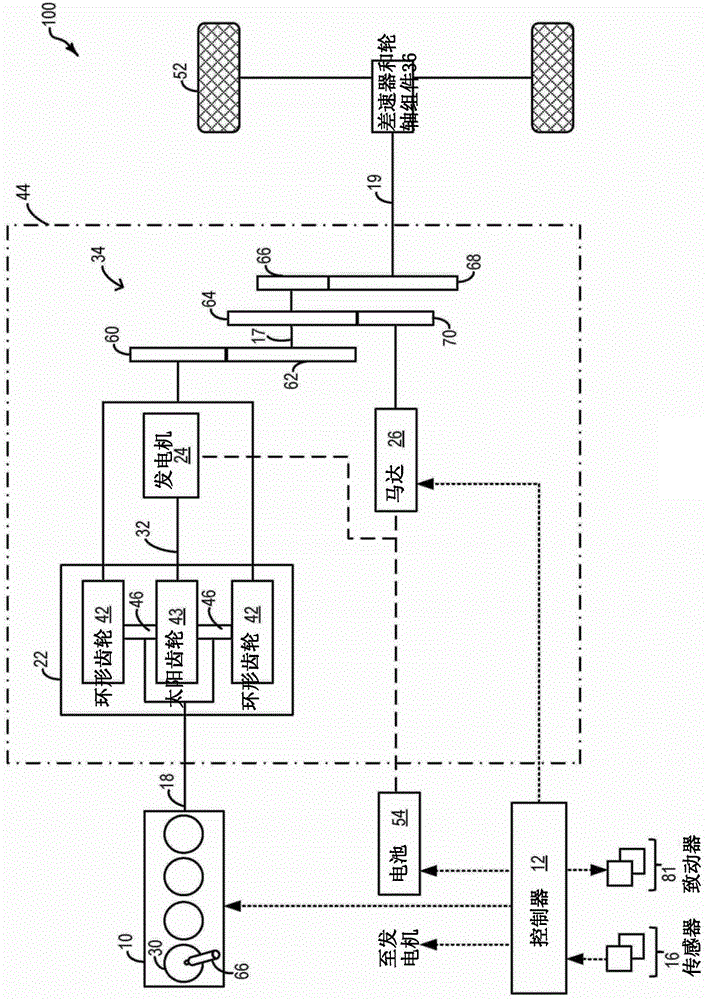
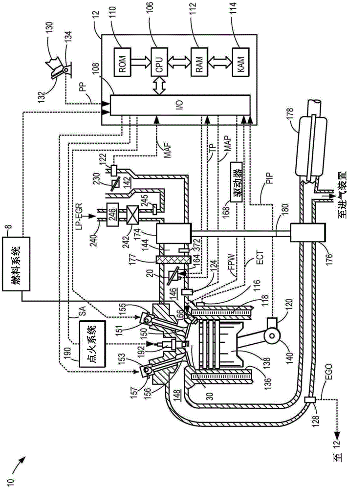
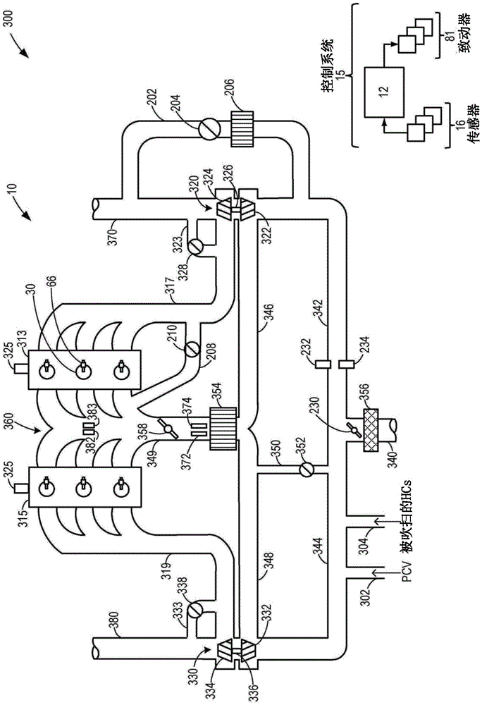
[0016] The following description refers to the use of hybrid vehicle systems such as figure 1 vehicle system) motor / generator to accelerate from the engine (such as Figure 2-3 engine system) systems and methods for purging EGR. When operating a hybrid vehicle in engine mode with EGR flowing, EGR delivery to the engine may need to be rapidly reduced in response to reduced engine load. During such conditions, the controller can be configured to execute control routines such as Figure 4 An example routine to disable fuel to the engine and use motor torque to propel the vehicle. Additionally, the controller may use the motor torque to spin up the unfueled engine for a period of time until the EGR is sufficiently purged from the engine's intake manifold. Alternatively, if the vehicle system battery is capable of accepting a charge, the controller may disable EGR and operate the engine with the EGR valve closed while storing excess engine torque generated as battery charge. re...


PUM


Abstract

Methods and systems are provided for expediting EGR purging in a hybrid vehicle during transient operations, such as tip-out to lower load conditions. In response to decreasing engine torque demand, engine fueling is disabled and a motor is used to spin the engine unfueled until a desired LP-EGR rate is achieved. Alternatively, engine operation is maintained with EGR disabled until the desired LP-EGR rate is achieved, and the excess engine torque generated is stored in a system battery.

Description

technical field [0001] The present application relates to methods and systems for improving purging of low pressure EGR from an engine during light load operation. Background technique [0002] Exhaust gas recirculation (EGR) systems recirculate a portion of exhaust gas from the engine exhaust to the engine intake system to improve fuel economy and vehicle emissions by reducing throttling losses and combustion temperatures. In turbocharged direct injection engines, a low pressure EGR (LP-EGR) circuit may be implemented. The LP-EGR circuit recirculates exhaust gas from the exhaust passage downstream of the turbine to the intake passage upstream of the turbocharger compressor. [0003] However, due to the pre-compressor position of EGR delivery, there may be a significant transmission delay between the EGR valve and the combustion chamber. Specifically, exhaust residues may need to travel through the turbocharger compressor, high pressure air induction duct, charge air coole...

Claims


Application Information

Patent Timeline
Patent Type & Authority Applications(China)
IPC IPC(8): F02D21/08F02M25/07
CPCF02D41/0065F02D41/042F02N11/0844F02M25/08F02D13/02F02D41/0055F02D2041/0017F02D2250/24F02M26/02B60W10/06B60W10/08B60W20/16B60W2510/244B60W2510/068B60Y2400/442B60W2710/0644B60W2710/083B60W2540/10Y02T10/40Y02T10/62B60W20/00F02D17/04
Inventor D·J·斯泰尔斯S·L·鲍尔J·A·海蒂奇R·R·埃奥里奥G·苏妮拉
Owner FORD GLOBAL TECH LLC
Learn More