


Quick Research
Generate reliable direction feasibility study reports for your R&D in just a few steps.

Technical Q&A
Discover and master advanced knowledge NOW. Basics, ideas, possibilities, all at once.

Find Solutions
As an expert in R&D theories, this can generate solutions to your technical problems instantly.

Evaluate Feasibility
Analyze your overall solution with one click, know your potential R&D risks in advance.

Monitor Landscape
Get weekly tech updates, stay abreast of the latest tech innovations and key insights.
Forming process of vertical shared exhaust duct
A molding process and exhaust duct technology, applied in vertical pipelines, building components, buildings, etc., can solve the problem of insufficient vertical shared exhaust ducts, and reduce yard and transportation costs, labor costs, and safety risks. small effect
- Summary
- Abstract
- Description
- Claims
- Application Information
AI Technical Summary
Problems solved by technology
Method used
Image

Examples
Embodiment 1
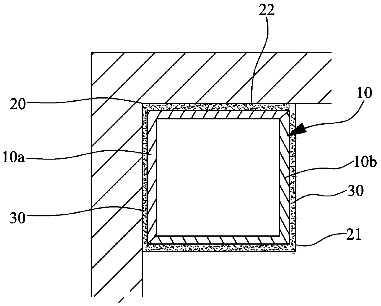
[0044] figure 1 , is a top view of the vertical common exhaust duct provided by Embodiment 1 of the present invention. The vertical shared exhaust duct 10 is formed in the corresponding preset hole 21 on the floor of the inner corner 20 of the floor room. Viewed from its cross section, the vertical shared exhaust duct is formed by the butt joint of two L-shaped thin-walled members, one of which is L-shaped An air inlet (not shown in the figure) is provided on the thin-walled member for installing a check valve. Here, for the convenience of description, the inner L-shaped thin-walled member is named as the first L-shaped thin-walled member 10a, and the outer L-shaped thin-walled member is named as the second L-shaped thin-walled member 10b. Here, the first L-shaped thin-walled member 10a and the second L-shaped thin-walled member 10b have the same structure, and the words "first" and "second" here are only used to distinguish the inner side from the outer side.
[0045] Fig...
Embodiment 2
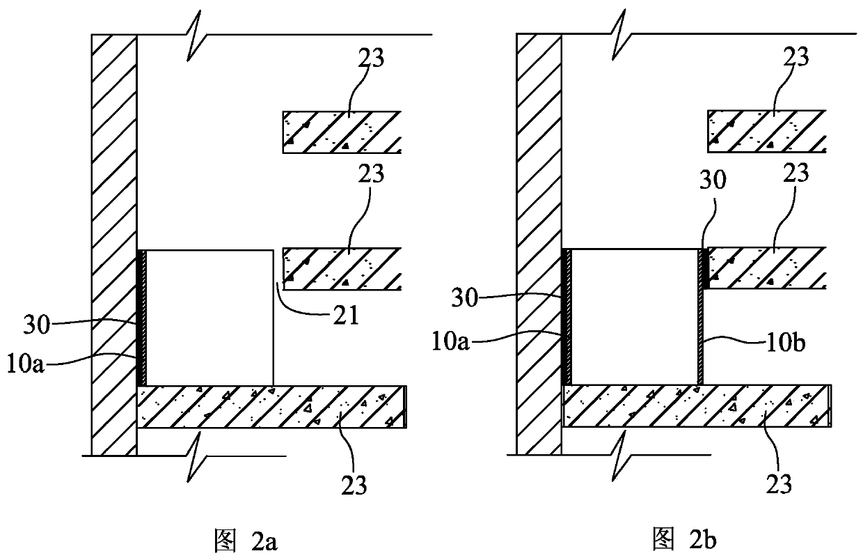
[0058] Figure 5a to Figure 5d , is a cross-sectional schematic diagram of the forming process of the vertical common exhaust channel provided by Embodiment 2 of the present invention. This embodiment also takes the forming of the vertical shared exhaust duct between two floors of a residence as an example for illustration. The forming process of other floors is the same as this embodiment, and will not be described in detail here. Moreover, this embodiment is described by taking an example in which the exhaust ducts on each floor are butt-jointed and formed by a first L-shaped thin-walled member 10a and a second L-shaped thin-walled member 10b.
[0059] Figure 5a , first lean against the first L-shaped thin-walled member 10a on the two wall surfaces 22 of the inner corner 20 of the room on the lower floor. In order to ensure the reliability of the adjacent installation, the two outer walls of the first L-shaped thin-walled member 30a and the two walls 22 of the inner corne...
Embodiment 3
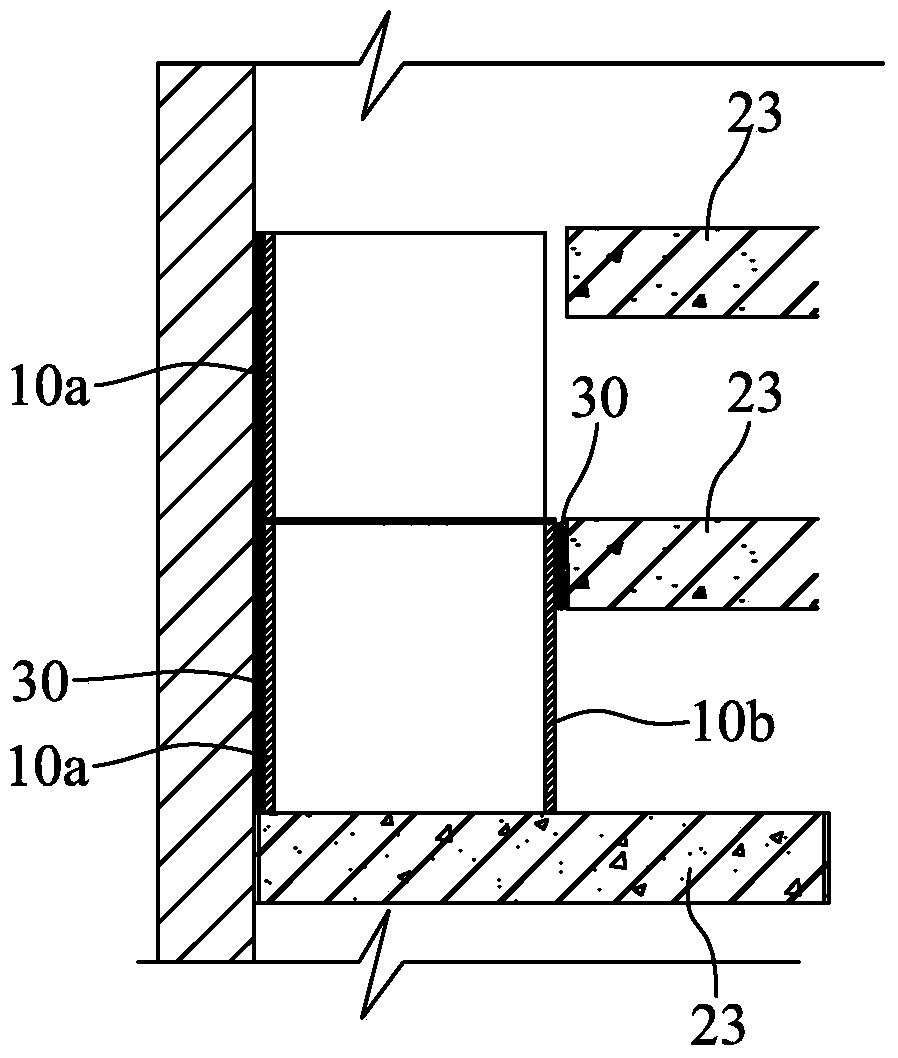
[0066] Figure 6 , is a longitudinal cross-sectional view of the vertical shared exhaust duct provided by Embodiment 3 of the present invention. In this embodiment, the exhaust duct on each floor is formed by butting two first L-shaped thin-walled components and two second L-shaped thin-walled components. In this way, compared with the first embodiment, the weight of each L-shaped thin-walled member is lighter, and it is easier to transport and install. Here, one floor is taken as an example for illustration, and the other floors are the same, so details are not repeated here. When forming the exhaust duct on this floor, first perform step S1, first fix the first first L-shaped thin-walled member 10a, and then perform step S2, that is, fix the first first L-shaped thin-walled member 10a again The first second L-shaped thin-walled member 10b that is docked, and then repeat step S1, superimpose the second first L-shaped thin-walled member 10a on the first first L-shaped thin-w...
PUM
 Abstract
Description
Claims
Application Information
 - R&D Engineer
- R&D Manager
- IP Professional
- Industry Leading Data Capabilities
- Powerful AI technology
- Patent DNA Extraction
Browse by: Latest US Patents, China's latest patents, Technical Efficacy Thesaurus, Application Domain, Technology Topic, Popular Technical Reports.
© 2024 PatSnap. All rights reserved.Legal|Privacy policy|Modern Slavery Act Transparency Statement|Sitemap|About US| Contact US: help@patsnap.com