
Light source apparatus and image projection apparatus

A lighting source and light source technology, applied in lighting devices, lighting device parts, image communication, etc., can solve the problems of easy adhesion of dust and easy entry of fluorescent bodies, so as to suppress the decline of light utilization efficiency and prevent the decline of service life. , the effect of suppressing temperature rise

Active Publication Date: 2015-05-20
RICOH KK
View PDF7 Cites 20 Cited by
  • Summary
  • Abstract
  • Description
  • Claims
  • Application Information

AI Technical Summary

Problems solved by technology

However, it is easy for external dust to enter in this way, so that dust is easy to adhere to the phosphor

Method used


Image

  • Light source apparatus and image projection apparatus
  • Light source apparatus and image projection apparatus
  • Light source apparatus and image projection apparatus

Examples


Embodiment Construction

[0031] Embodiments of the present invention are described below with reference to the drawings.

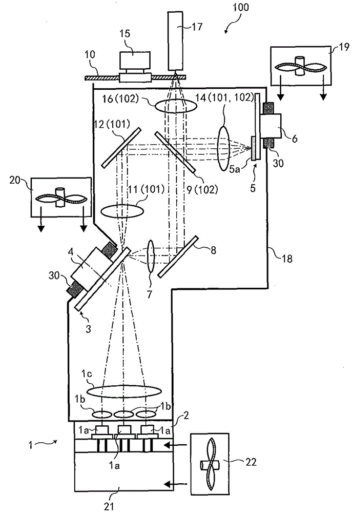
[0032] figure 1 The illustrated illumination light source device 100 includes a light source unit 1, an optical path switching disc 3, an exciting light converging optical system 101 for converging light emitted from the optical path switching disc 3, a phosphor wheel 5 constituting a phosphor, and a beam splitter. 9, and condenser lens 14 and 16.

[0033] Each of the above parts will be described in detail below.

[0034] The light source unit 1 includes a laser diode (LD) 1a as a light source for emitting laser light (excited light), a coupler 1b, and a condenser lens 1c.

[0035] A plurality of laser diodes 1a are provided on the laser diode holder 2, and corresponding to each laser diode 1a, a plurality of coupling mirrors 1b are correspondingly provided.

[0036] The laser light emitted by the laser diode 1a is converged by the coupling mirror, and then goes to the condens...


PUM


Abstract

A light source apparatus (100) includes a light source (1a) to emit excitation light; a phosphor (5) as a rotatable wavelength convertor; a motor (6) to drive the phosphor (6); an excitation light condensing optical system (101) to condense the excitation light emitted from the light source (1a) onto the phosphor (5); and a casing (18) having a closed space to encase the light source (1a), the phosphor (5), and the excitation light condensing optical system (101), and at least a part of the motor (6) while a remaining part of the motor (6) being protruded to an external space of the casing (18).

Description

technical field [0001] The invention relates to an illuminating light source device and an image projection device, in particular to reducing the influence of heating of components used in these devices and preventing dust from adhering to the components. Background technique [0002] Projectors are often used as image projection devices now, and images are projected onto screens for audio-visual purposes. The projected image is generally based on a personal computer screen or a recorded screen, and furthermore, based on image data stored in a memory card or the like. [0003] The above-mentioned projector can converge the light emitted by the light source to a micromirror display element called a digital micromirror device (DMD) or a liquid crystal panel, and display a color image on a screen. [0004] In the past, the above-mentioned projectors mainly used high-intensity discharge lamps as light sources, but in recent years, projectors have often used solid-state light-em...

Claims


Application Information

Patent Timeline
Patent Type & Authority Applications(China)
IPC IPC(8): G03B21/20G03B21/16
CPCG03B21/145G03B21/16G03B21/204G03B33/08H04N9/3114F21V14/08
Inventor 西森丈裕藤田和弘村井俊晴高桥达也
Owner RICOH KK
Learn More